Chapter 1: Product Summary
This chapter provides an overview of the ASF1-30.
1.1 Checking the Accessories
Please check that all the accessories are included.
If you find any accessories are missing, please contact the distributor from whom you purchased this product immediately.
Accessories for the ASF1-30 packaging box
|
Item |
Q'ty |
Item |
Q'ty |
|
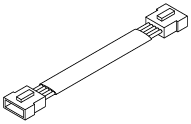
Connection cable
|
1 pc. |
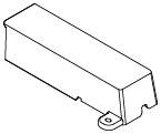
Cable cover
|
1 pc. |
|
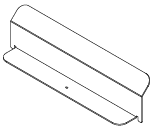
Extension tray
|
1 pc. |
Accessories for the packaging box of the paper output tray
|
Item |
Q'ty |
Item |
Q'ty |
|
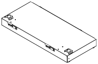
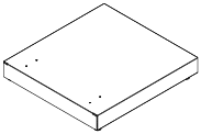
CE8000 base
|
1 pc. |
SETUP MANUAL / Request for firmware
|
1 set |
|
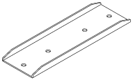
ASF1-30 base
|
1 pc. |
Base connecting parts
|
2 pcs. |
|
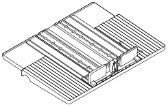
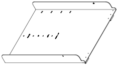
Paper output tray
|
1 pc. |
Media Stopper
|
1 pc. |
|
Tray fixing bracket (A)
|
1 pc. |
Tray fixing bracket (B)
|
1 pc. |
|
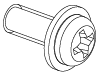
Screw A
|
3 pcs. |
Screw B
|
12 pcs. |

.png)
.png)

* In addition, various other information may be attached.
* Accessories may vary depending on the sales region.
For details, please contact the distributor from whom you purchased this product.
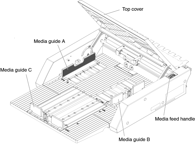
1.2 Nomenclature
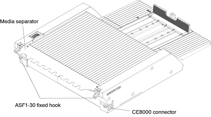
ASF1-30 fixed hook ........... This is a hook to secure the ASF1-30 and CE8000-40.
CE8000 connector ............. This is the connector for connecting the ASF1-30 to CE8000-40.
Media guide A/B/C .............. This is an adjustment guide to fit the width and length of the media you are loading.
Media feed handle .............. A handle for manually feeding media or feeding media that has stopped midway.
Top cover ............................ This opens and closes when feeding or removing media.
Media separator .................. This is the part that feeds media to the CE8000-40.
1.3 Assembling
How to assemble the Paper output tray
Tools to be provided by the customer
• Phillips head screwdriver (No. 2)
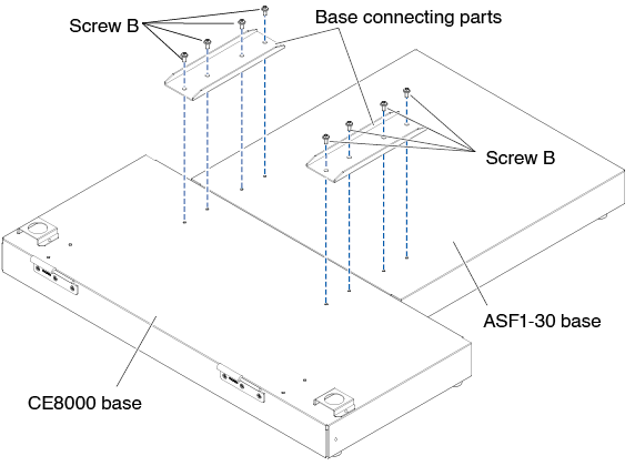
1. Using a Phillips screwdriver, attach the CE8000 base to the ASF1-30 base with the two Base connecting parts and eight Screws B.
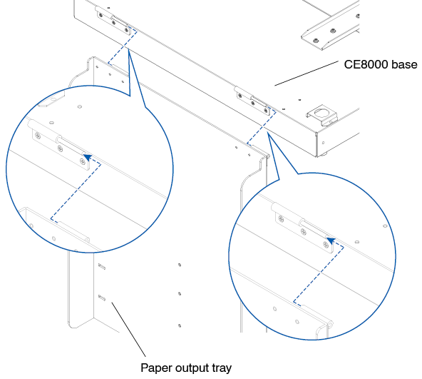
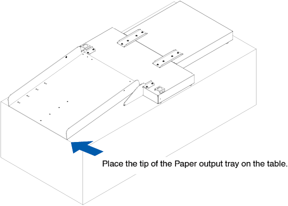
2. Insert the two hinges of the Paper output tray into the two hinges of the CE8000 base.
After inserting the hinges, hang the Paper output tray down.
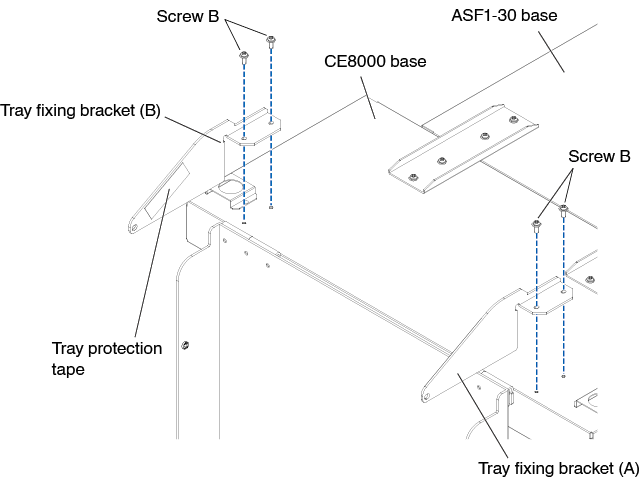
3. Use a Phillips screwdriver to attach the Tray fixing bracket (A) and the Tray fixing bracket (B) with the four Screws B.
After installing the Tray fixing brackets, if you will be using the Paper output tray at a 45-degree angle, go to step 4. If you will be using it on a tabletop, go to step 5.

When attaching the Tray fixing bracket (A) and (B), make sure that the Tray protection tape that stuck on the Tray fixing bracket (A) and (B) are positioned on the inside before attaching them.
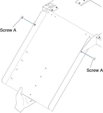
4. When fixing the Paper output tray at a 45-degree angle.
Use the two Screws A to fix the Paper output tray while supporting it with your hands.
The output tray can be extended from the table and used as a ramp.
• It is recommended that you use the output tray at a fixed 45-degree angle.
• The media may protrude from the paper output tray due to its curling or hardness.
If this occurs, set the eject speed of the CE8000-40 to [SLOW].
5. When using the Paper output tray on a tabletop.
The Output tray can be placed and used on a tabletop.
The properties of the media and static electricity may affect the media ejection.
In such cases, it is recommended to use it at a fixed angle of 45 degrees.
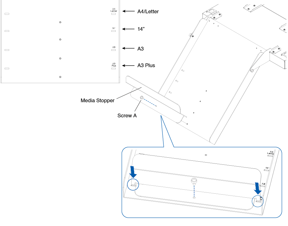
6. Attach the Media stopper.
The media size is listed on the Paper output tray, insert the left and right protrusions on the Media stopper according to the media size to be used into the notches on the Paper output tray and fixed it with Screw A.
How to set up the CE8000-40
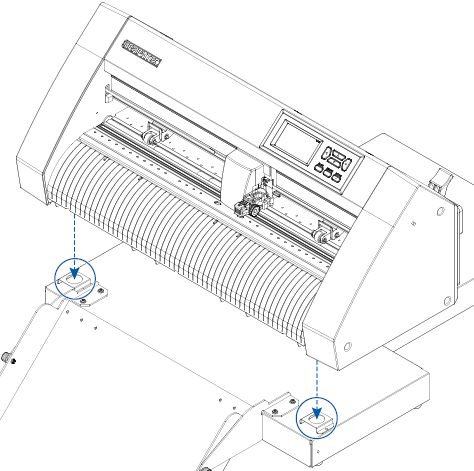
1. Insert the feet of the CE8000-40 into the positioning holes on the CE8000 base.
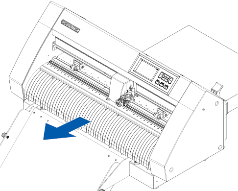
2. After installing the CE8000-40, press the CE8000-40 in the direction of the arrow in the figure below.
How to connect the CE8000-40
Check that the CE8000-40's power switch is off (the " " side is pressed down).
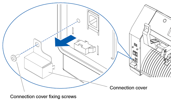
1. Use a Phillips screwdriver to remove the ASF1-30 Connection cover mounting screws, and then remove the ASF1-30 Connection cover.
• Please prepare your own Phillips screwdriver.
• The Connection cover fixing screw will be used again in step 4.
• Please keep the removed Connection cover in a safe place.
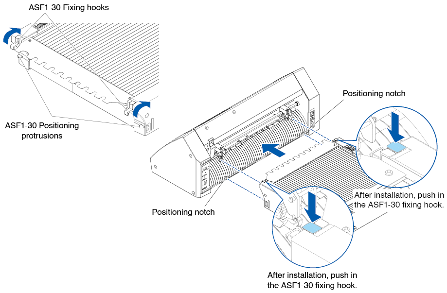
2. Install the ASF1-30.
Raise the ASF1-30 fixed hook, insert the ASF1-30 Positioning protrusions into the CE8000-40, and then push the ASF1-30 fixed hook in from above.
3. Attach the Connection cable.
The shapes of both connectors on the Connector cable are same, it can be connected to both the CE8000-40 and the ASF1-30.
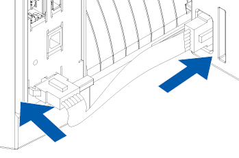
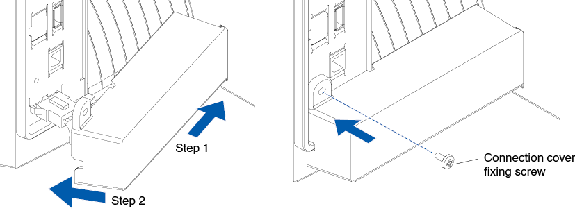
4. Attach the Cable cover.
Insert the Cable cover into the notch on the ASF1-30 and fixed it to the CE8000-40 using the Connection cover fixing screw.
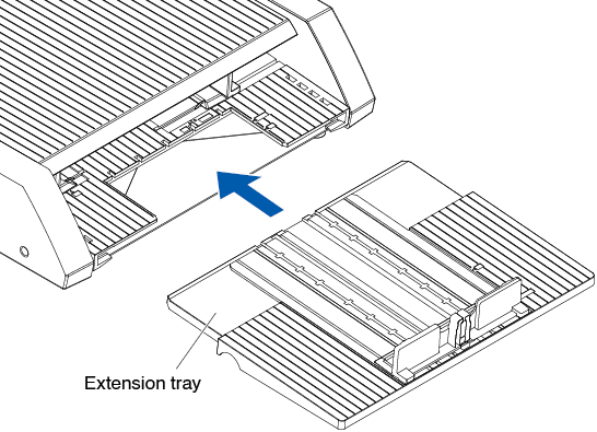
5. Insert the Extension tray.
When inserting the Extension tray, make sure there is nothing under the Extension tray.
If there is anything under the Extension tray, the media will not be feed properly.
Assembly video
This is a video explaining the assembly procedures of the automatic sheet feeder unit.