Chapter 3: ASF1-30 dedicated menu
This chapter describes the dedicated menu displayed when ASF1-30 is connected.
3.1 CE8000-40 Specifications
When an ASF1-30 is connected, ASF1-30 dedicated functions are displayed on the CE8000-40 touch panel and some CE8000-40 functions are restricted.
This section explains the ASF1-30 dedicated menu.
For information about the CE8000-40 common menu, refer to the CE8000 Series User's Manual.
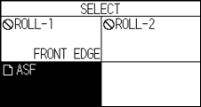
MEDIA SELECTION screen
Select [SHEET] when loading sheet media.
[SHEET] is displayed when media is loaded in CE8000-40.
Select [ASF] when feeding media from ASF1-30.
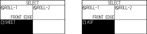

• When ASF1-30 is connected, [ROLL 1] and [ROLL 2] are not available.
• [ASF] is displayed when no media is loaded in the CE8000-40.
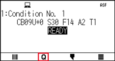
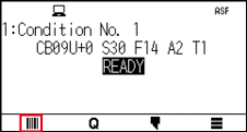
Icon on the top right of the READY screen (ASF1-30 connection indicator)
When the ASF1-30 is connected, the [ASF] icon is displayed in the top right corner of the HOME screen.
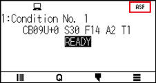
If [ASF] icon is not displayed, please check if there are any problems with the connection between CE8000-40 and ASF1-30.
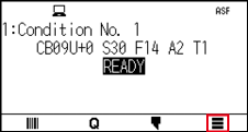
ASF menu
When ASF1-30 is connected, the [ASF] menu is displayed on the MENU screen.
Operation
1. Press the [ ] icon.
2. The [ASF] menu is displayed.
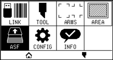
The [MEDIA] icon is replaced with the [ASF] icon.
When the ASF1-30 is connected, the settings in the [MEDIA] menu are not available.
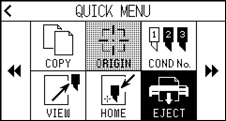
LOAD/EJECT in QUICK MENU
When the ASF1-30 is connected, the [LOAD] icon or [EJECT] icon is displayed in the [QUICK MENU].
If no media is loaded, the [LOAD] icon is displayed.
If media is loaded, the [EJECT] icon is displayed.
When feeding media from ASF1-30
Operation
1. Press the [ ] icon.
2. Press the [LOAD] icon.

When ejecting the media that has been loaded
Operation
1. Press the [] icon.
2. Press the [EJECT] icon.
Detailed position adjustment of CE8000-40 push roller
Operation
1. Load the media in the ASF.
For details, refer to “2.2 Loading the Media”.
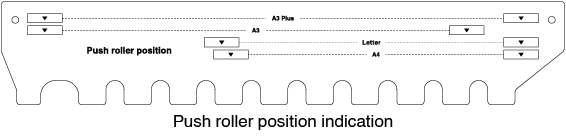
2. Lower the media set lever of the CE8000-40 and adjust the position of the push rollers of the CE8000-40 to match the push roller position indication of the ASF1-30.
For how to operate the media set lever and adjust the position of the push rollers of the CE8000-40, refer to the CE8000 Series User’s Manual.
3. Raise the media set lever of the CE8000-40 and select ASF on the [SELECT] screen.
4. Press the [].
5. Press the [LOAD].
6. Press the left POSITION key to move the tool carriage to a position where you can see the push rollers.
7. Check the position of the push rollers.
If you want to adjust the position of the push rollers, lower the media set lever and then adjust them.
8. After adjustments are complete, remove the media.
ORIGIN in QUICK MENU
When ASF1-30 is connected, the [ORIGN] icon is disabled.
COPY in QUICK MENU
When the ASF1-30 is connected, the [MEDIA CHANGE MODE] in the [COPY] menu cannot be changed.
The ASF1-30 always operates at [ON].
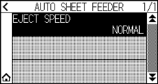
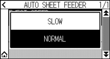
Eject speed setting
When the eject speed is set to [NORMAL], the media may not fit in the paper output tray due to its curling or hardness. In this case, set the eject speed to [SLOW].
Operation
1. Press the [] icon.
2. Press the [ASF].
3. Press [EJECT SPEED].
4. Press the eject speed you want to use.
5. Press the [ ] icon.
 It will return to HOME screen.
3.2 Specifications of included software
When you select ASF1-30 as the model to be connected, ASF1-30 dedicated functions are displayed in our cutting plotter software (Cutting Master 5/Graphtec Studio 2).
This section explains the ASF1-30 dedicated menu.
For information about the CE8000-40 common menu, refer to the User's Manual for our cutting plotter software (Cutting Master 5/Graphtec Studio 2).
MODEL SELECTION screen
When using the ASF1-30, select [CE8000-40+ASF1] in the model name.
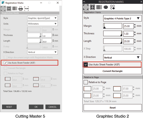
Registration mark creation option
When you select the [Use Auto Sheet Feeder (ASF)] on the [REGISTRATION MARK (Registration Mark)] screen, the settings for ASF1-30 are reflected on the screen.
This can prevent registration marks and barcodes that cannot be used with ASF1-30 from being created.
First registration mark positioning option
When you specify [Scanning start position of Registration Marks] on the CUTTING screen and then you start cutting with registration marks, the CE8000-40 automatically moves to the position of the first registration mark and scan it.
The first registration mark position in the design document is set as the default in [Reg Mark origin print position X (and Y)].
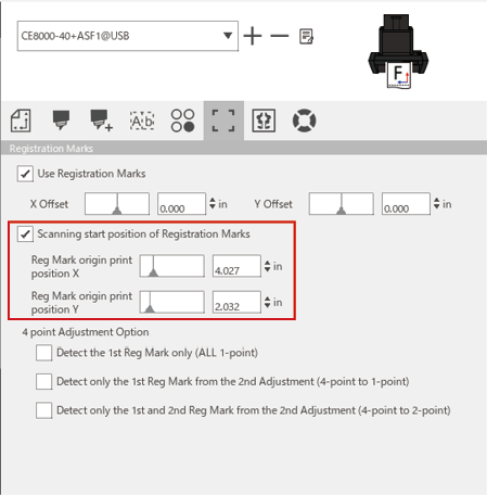
This operates on the assumption that the push rollers are set to the positions specified in the CE8000 series User’s Manual.
If scanning of the first registration mark fails, adjust the value of [Reg Mark origin print position X (and Y)].
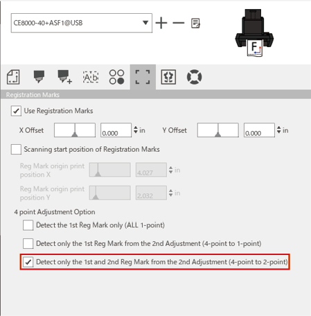
Option to scan two registration marks with four registration marks
When selecting the [Detect only the 1st and 2nd Reg Mark from the 2nd Adjustment (4-point to 2-point)] on the CUTTING screen, all four registration marks are scanned on the first sheet, and only two registration marks are scanned from the second sheet onwards.
The correction for the first sheet is applied to cutting from the second sheet onwards.
This function is applied when cutting the same data repeatedly, such as in continuous operation or copy from the CE8000-40.
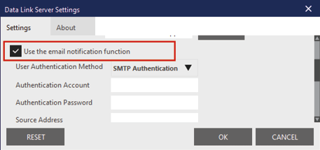
Continuous operation email notification option
When selecting the [Use the email notification function] on the [Data Link Server Settings] screen, an email notification is sent to the specified address when continuous operation using [Data Link Server] stops.
An email is sent if continuous operation is paused because the media runs out, or if continuous operation stops due to a registration mark scan failure, etc.
Basic workflow for cutting with registration marks
Operation
1. Refer to "Operation with Barcode and Data Link Server Feature" – "Basic Workflow for Registration Marks" in the Cutting Master 5/Graphtec Studio 2 User's Manual and proceed up to "STEP 3".
2. Follow the steps below to operate "STEP 4".
(1) Load the printed media in the ASF1-30.
(2) Raise the media set lever.
(3) Press the [ASF] icon.
(4) The [READY] screen appears.

(5) Perform the operations from "3" onwards in "STEP 4".
When you want to cut the same data repeatedly, specify the number of cuts.
When you want to specify the number of cuts from the software, set it in [Repeat Job] on the [General] tab.
When you want to specify the number of cuts from the CE8000-40, set it in the COPY function.
For the COPY function of the CE8000-40, refer to the CE8000 Series User’s Manual (4.2 Copy (Duplicate Cutting) – When media change mode is ON).
When using the COPY function of the CE8000-40, set the number of cuts in Cutting Master 5/Graphtec Studio 2 to [1].
Basic workflow for cutting with barcodes
The [Standard] barcode cannot be used.
Select the [Continuous Operation] barcode and set the [Barcode Location] to the [Front Edge Only] to use it.
The [Roll Media] barcode has been renamed to [Continuous Operation] barcode.
Data Link Function (Continuous Operation Using Barcode) Workflow
Operation
1. Refer to "Operation with Barcode and Data Link Server Feature" – "Data Link Workflow for Continuous Cutting (Barcode Data Management)" in the Cutting Master 5/Graphtec Studio 2 User's Manual and proceed up to "STEP 5".
2. Follow the steps below to operate "STEP 6".
(1) Press the [] icon.
(2) Press the [LINK] icon.
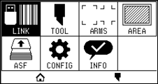
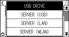
(3) Press the [DESTINATION] icon.
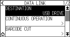
(4) Select the interface that connects the Data Link Server to the Cutting Plotter.
(5) Press the [] icon.
It will return to HOME screen.
3. Follow the steps below to operate "STEP 7".
(1) Load the printed media in ASF1-30.
(2) Press the [ ] icon.
Media is fed from ASF1-30.
Barcode scan starts and the corresponding data is read from the Data Link Server.
Registration mark scan starts, and cutting begins once all registration marks have been scanned.
• A buzzer sounds when continuous operation stops (when the media loaded in ASF1-30 runs out).
• For continuous operation, it is recommended to use the default start mark position.
If scanning of the start mark fails, adjust the print position of start mark.