1.1 Checking the Accessories
Accessories
|
Item |
Q'ty |
Item |
Q'ty |
|
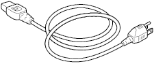
Power cable
|
1 pc |
TO ENSURE SAFE AND CORRECT USE
|
1 sht. |
|
Notice
|
1 sht. |
Cutter plunger (PHP33-CB09N-HS)
|
1 pc |
|
Cutter blade (CB09UB (1P))
|
1 pc |
Wireless LAN module
|
1 pc |
|
Wireless LAN module cover
|
1 pc |
Screws for wireless LAN module
|
2 pcs |
|
Accessory case
|
1 pc |


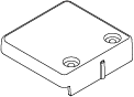

* The accessory case has a magnet. Please attach it in a convenient location.
* In addition, various information may be attached.
* Accessories may vary depending on the sales area. For details, please contact the distributor where you purchased.
Dedicated accessories
|
CE8000-40 |
CE8000-60 |
CE8000-130 |
|||
|
Item |
Q'ty |
Item |
Q'ty |
Item |
Q'ty |
|
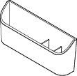
Roll-medium tray
|
1 set |
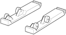
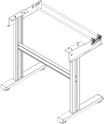
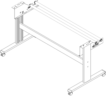
Stand
|
1 set |
Stand
|
1 set |
* Dedicated accessories may vary depending on the sales area. For details, please contact the distributor where you purchased.
1.2 Nomenclature
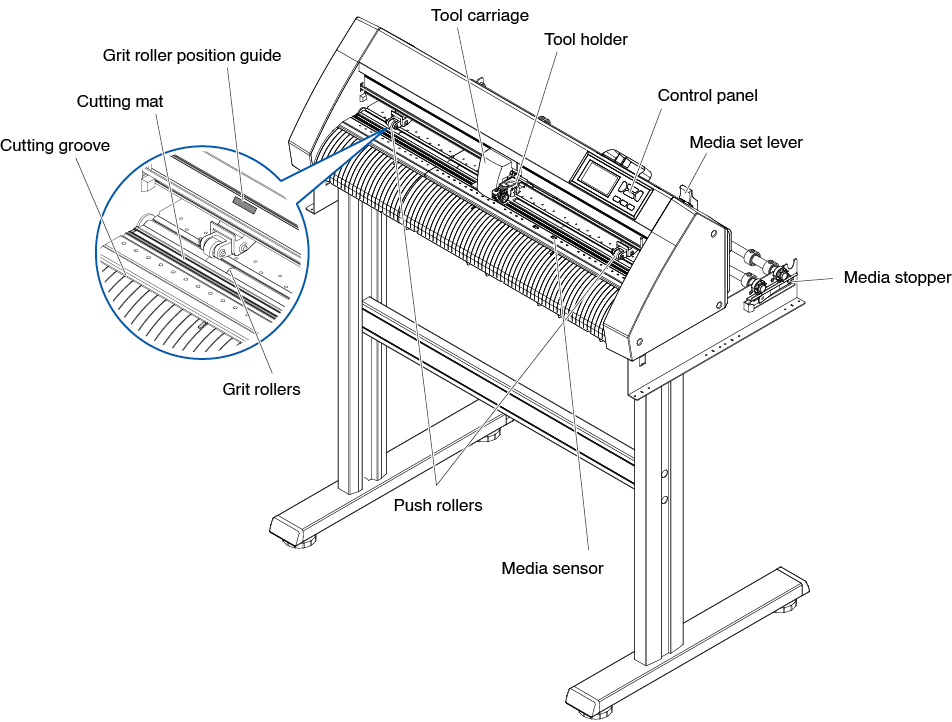
Front view: CE8000-40
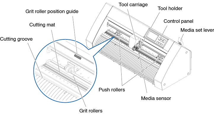
Control panel
Used to access various plotter functions.
Media set lever
Used to raise or lower the push rollers during the loading or unloading of media.
Tool carriage
Moves the cutter-pen or plotting pen across the media during cutting or plotting.
Tool holder
Holds the cutter-pen or plotting pen and moves it up or down.
Media sensor
Used to scan the leading edge of the media.
Push rollers
Rollers that push the media against the grit rollers.
Grit roller position guide
A roller position guide is affixed to the front side of the rail, which shows the position of each grit roller. Use these alignment marks as an aid in locating the push rollers.
Grit rollers
Feeds the media back and forth.
Cutting mat
The cutter blade moves on this cutting mat.
Cutting groove
Use this groove to cut out (die cut) or cross cut.
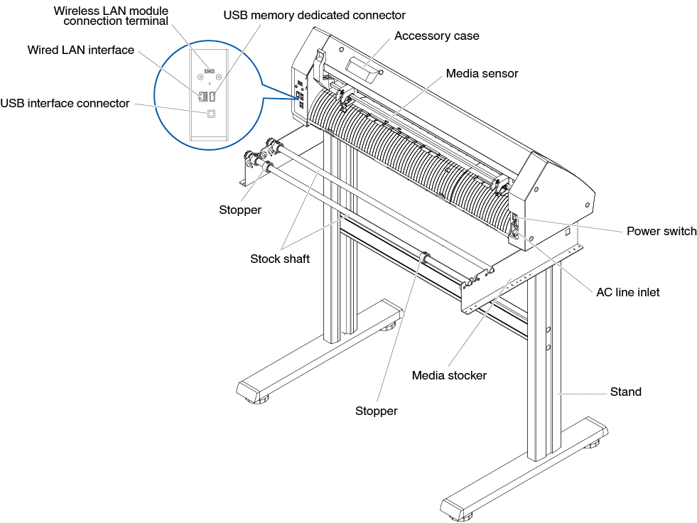
Rear view: CE8000-40
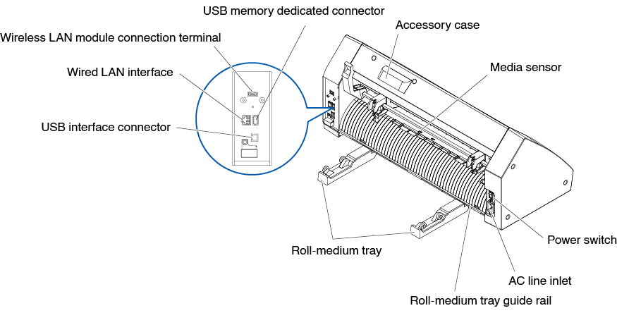
Power switch
Used to turn the plotter on and off.
AC line inlet
Inlet where the power cable is connected.
Roll-medium tray
A tray to set media in.
Roll-medium tray guide rail
A rail to set the roll media tray in.
Accessory case
Space for temporary storage of accessories such as cutter blades and cutter plungers.
* The accessory case has a magnet. Please attach it in a convenient location.
Media sensor
Used to scan the trailing edge of the media.
USB interface connector
Used to connect the plotter to the computer with a USB interface cable.
Wireless LAN module connection terminal
This is the terminal for connecting the wireless LAN module to the plotter.
* A cover is attached to protect the terminals at the time of purchase.
Wired LAN interface
This connector is used when connecting this plotter via network (wired LAN).
* Wired LAN support varies depending on the sales area.
USB memory dedicated connector
This is a dedicated connector for USB memory.
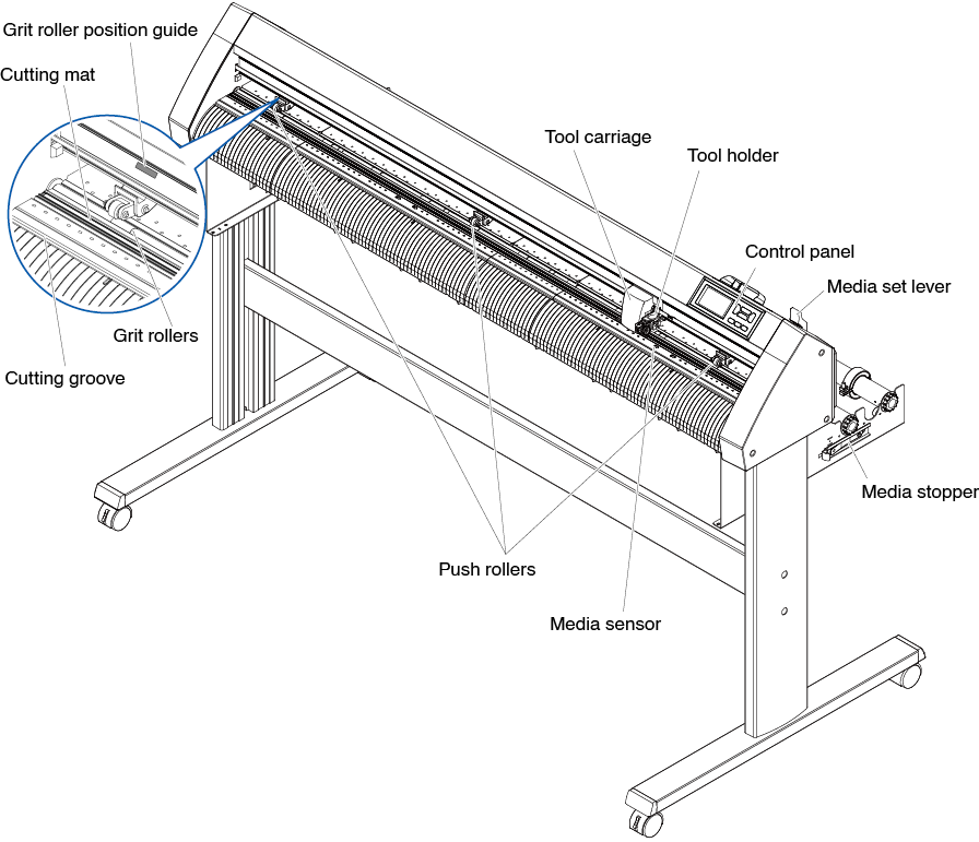
Front view: CE8000-60
Control panel
Used to access various plotter functions.
Media set lever
Used to raise or lower the push rollers during the loading or unloading of media.
Tool carriage
Moves the cutter-pen or plotting pen across the media during cutting or plotting.
Tool holder
Holds the cutter-pen or plotting pen and moves it up or down.
Media sensor
Used to scan the leading edge of the media.
Push rollers
Rollers that push the media against the grit rollers.
Media stopper
This stops the stock shaft from spinning when setting roll paper (media). It is utilized when pulling roll media straight out.
Grit roller position guide
A roller position guide is affixed to the front side of the rail, which shows the position of each grit roller. Use these alignment marks as an aid in locating the push rollers.
Grit rollers
Feeds the media back and forth.
Cutting mat
The cutter blade moves on this cutting mat.
Cutting groove
Use this groove to cut out (die cut) or cross cut.
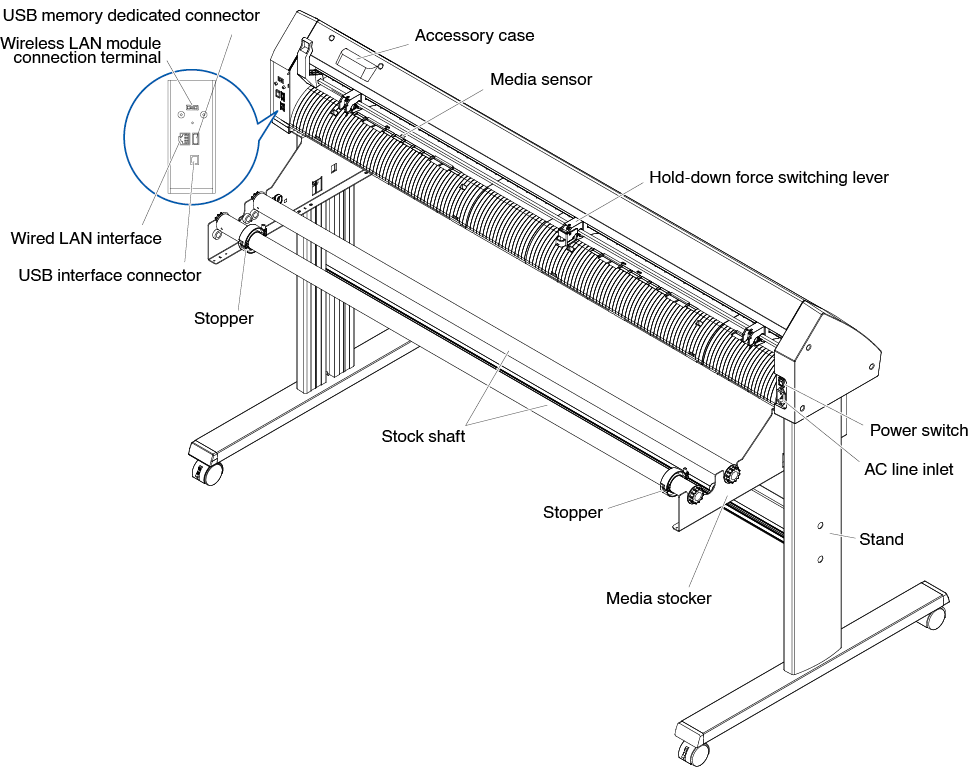
Rear view: CE8000-60
Power switch
Used to turn the plotter on and off.
AC line inlet
Inlet where the power cable is connected.
Media stocker
A stock to set roll media in.
Stock shaft
A roller that takes in roll media.
Stopper
Keeps set roll media in place.
Stand
A stand to put the machine on.
Accessory case
Space for temporary storage of accessories such as cutter blades and cutter plungers.
* The accessory case has a magnet. Please attach it in a convenient location.
Media sensor
Used to scan the trailing edge of the media.
USB interface connector
Used to connect the plotter to the computer with a USB interface cable.
Wireless LAN module connection terminal
This is the terminal for connecting the wireless LAN module to the plotter.
* A cover is attached to protect the terminals at the time of purchase.
Wired LAN interface
This connector is used when connecting this plotter via network (wired LAN).
* Wired LAN support varies depending on the sales area.
USB memory dedicated connector
USB memory dedicated connector.
Front view: CE8000-130
Control panel
Used to access various plotter functions.
Media set lever
Used to raise or lower the push rollers during the loading or unloading of media.
Tool carriage
Moves the cutter-pen or plotting pen across the media during cutting or plotting.
Tool holder
Holds the cutter-pen or plotting pen and moves it up or down.
Media sensor
Used to scan the leading edge of the media.
Push rollers
Rollers that push the media against the grit rollers.
Media stopper
This stops the stock shaft from spinning when setting roll paper (media). It is utilized when pulling roll media straight out.
Grit roller position guide
A roller position guide is affixed to the front side of the rail, which shows the position of each grit roller. Use these alignment marks as an aid in locating the push rollers.
Grit rollers
Feeds the media back and forth.
Cutting mat
The cutter blade moves on this cutting mat.
Cutting groove
Use this groove to cut out (die cut) or cross cut.
Rear view: CE8000-130
Power switch
Used to turn the plotter on and off.
AC line inlet
Inlet where the power cable is connected.
Hold-down force switching lever
Switch the hold-down force of the push roller to two levels: medium and weak (OFF).
Media stocker
A stock to set roll media in.
Stock shaft
A roller that takes in roll media.
Stopper
Keeps set roll media in place.
Stand
A stand to put the machine on.
Accessory case
Space for temporary storage of accessories such as cutter blades and cutter plungers.
* The accessory case has a magnet. Please attach it in a convenient location.
Media sensor
Used to scan the trailing edge of the media.
USB interface connector
Used to connect the plotter to the computer with a USB interface cable.
Wireless LAN module connection terminal
This is the terminal for connecting the wireless LAN module to the plotter.
* A cover is attached to protect the terminals at the time of purchase.
Wired LAN interface
This connector is used when connecting this plotter via network (wired LAN).
* Wired LAN support varies depending on the sales area.
USB memory dedicated connector
USB memory dedicated connector.
1.3 Assembling
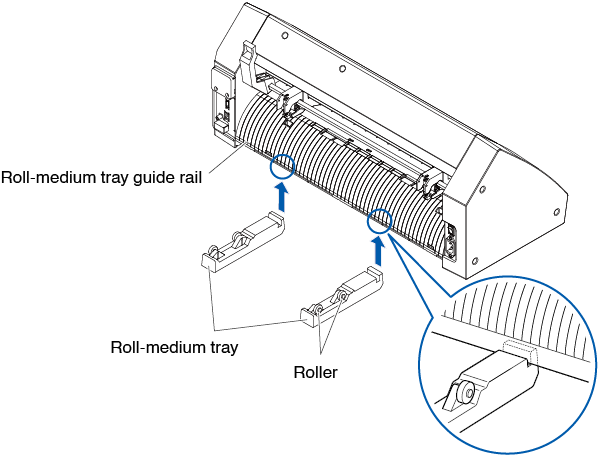
Mounting the Roll-medium tray
Mounting (CE8000-40)
1. Insert the roll-medium tray into the tray guide rail according to the media width you want to use.
Make sure the rollers on the tray are on the outside on both sides.
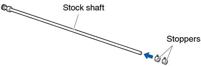
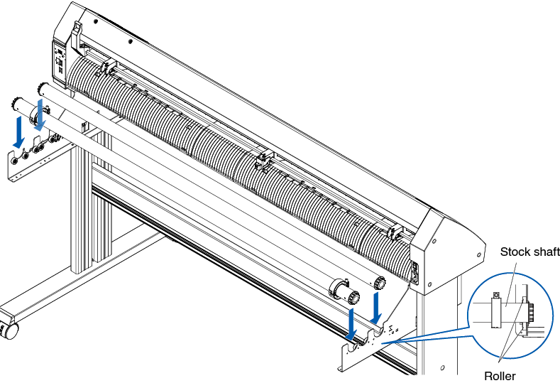
Mounting the stock shafts
Mounting (CE8000-60)
1. Set one stopper in the stock shaft. (Keep the stopper screws slightly loose.)
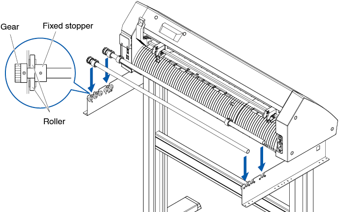
2. Put the side with the gear on the left side of the machine (looking from the back) and then slide the stock shaft into the media stocker.
Slide the media stocker in so that it is bookended by the gear and the fixed stopper.
Make sure the stock shaft touches the roller.
Change the insertion position of the rear stock shaft according to the roll diameter of the media you want to use.
Mounting (CE8000-130)
1. Set one stopper in the stock shaft. (Keep the stopper screws slightly loose.)
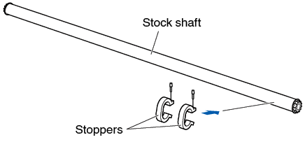
2. Slide the stock shaft into the media stocker.
Change the insertion position of the rear stock shaft according to the roll diameter of the media you want to use.
1.4 Connecting to the Computer
This section describes how to connect the plotter and the computer.
Use either a USB port, wireless LAN or wired LAN* to connect the plotter to a computer.
The driver software must be installed before connection.
* Wired LAN support varies depending on the sales area.
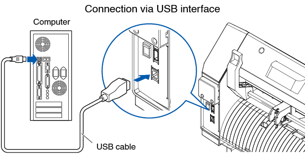
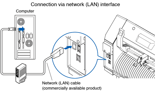
When using USB/Wired LAN
Connection
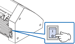
1. Check that the power switch is turned off (the " " side is pressed down).
2. Connect the plotter to the computer using the interface cable.
* This section explains in the CE8000-130.

See the “9.1 Setting Interface” for setting the interface.
When using wireless LAN
Connection
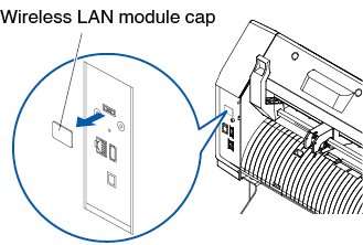
1. Check that the power switch is turned off (the "" side is pressed down).

2. Remove the wireless LAN module cap.
* This section explains in the CE8000-130.
3. Install the wireless LAN module to the wireless LAN connection terminal.
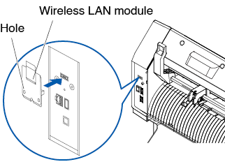
Make sure that the wireless LAN module is firmly installed all the way.
4. Secure the wireless LAN module cover and the wireless LAN module with screws using a phillips screwdriver.
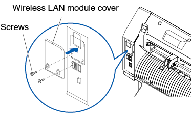
• Please prepare your own phillips screwdriver.
• For wireless LAN settings, see “9.2 Connecting via wireless LAN”