12.1 Select Connection Destination
Dedicated data created previously with application software etc. is output to the cutting plotter.
It can be saved in USB memory and output the data saved in USB memory, or output via server (personal computer) using network or USB cable.
Operation
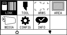
1. Press the [ ] icon.
2. Press the [LINK].
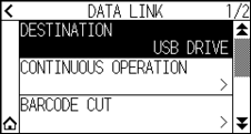
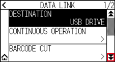
3. Press the [DESTINATION].

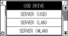
• “SERVER (LAN)” is displayed when the wired LAN module is installed.
• “SERVER (WLAN)” is displayed when the wireless LAN module is installed.
4. Press the connection destination you want to use.
5. Press the [ ] icon.
 It will return to HOME screen.
12.2 Data Link with USB Memory
Dedicated data created previously with application software etc. can be saved in the USB memory and output from the cutting plotter.
Data link can be performed by selecting data from the plotter menu.
• File name
– Only 1-byte alphanumeric characters (ASCII) are supported.
– Windows prohibited characters (¥, \, /, ;, *, ?, “, <, >, |, etc. are not available.
– Limit of the number of display characters is 25 characters. More characters than 25 can be displayed by scrolling.
– Extension is “xpf” and “plt”.
• Scroll is displayed after a few moments after selecting the item.
• The folder is surrounded by ‘<’ and ‘>’.
• Name is sorted in ascending order.
• Files and folders can be obtained up to 64.
• Files in the second level folder is not available.
• Practical examples of data links are also included in the separate “Cutting Master 5 User’s Manual” and “Graphtec Studio 2 User’s Manual”. Please refer to it as needed.
• Only FAT32 is supported as the USB memory format. NTFS and exFAT are not supported.
Operation
1. Insert the USB memory that saved the dedicated data to the plotter.
2. Press the [] icon.
3. Press the [LINK].
4. Press the [DESTINATION].
5. Press the [USB DRIVE].
6. Press the [ ] icon.

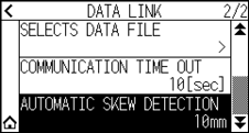
7. Press the [SELECTS DATA FILE].
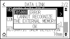
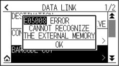
• If the USB memory is not inserted, the following is displayed.
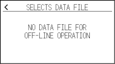
• If there is no data in the USB memory, the following screen is displayed.
8. Use the [] and [ ] icons to display the file to be used.
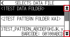
The string in parentheses <> is the folder name.
Press the folder name to display the files in the folder.
9. Press the file you want to use.
Start cutting with the selected file.
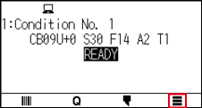
10. It will return to READY status when the cutting is completed.
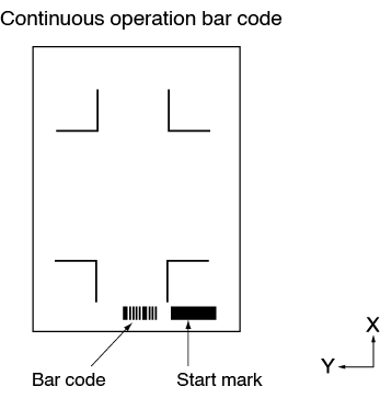
12.3 Output with a Bar Code
The information related to the output file is bar-coded using the Cutting Master 5 and Graphtec Studio 2, etc. and the barcode can be printed with the design and the registration marks.
When cutting with the cutting plotter, the bar code is scanned and the cut data (XPF) that has been saved to a USB memory that matches the bar code is detected.
Practical examples of data links are included in the “Cutting Master 5 User’s Manual” and “Graphtec Studio 2 User’s Manual”.
Please download each User’s Manual from the URL listed in “ Chapter 13 Cutting with supplied application software”.
Operation
1. Insert the USB memory that saved the dedicated data to the plotter.
2. Press the [] icon.
3. Press the [LINK].
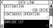
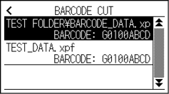
4. Press the [BARCODE CUT].
• If the USB memory is not inserted, the following is displayed.
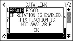
• When the Rotation is set to ON, the following display is displayed.
• When the Mirror is set to ON, the following display is displayed.
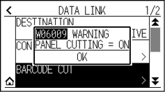
• When the Panel Cutting is set to ON, the following display is displayed.
5. Press the POSITION ( ,
,  ,
,  ,
,  ) key to move the tool to the start mark position.
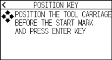
6. Confirm the tool position and press the [ENTER] key.
The bar code is scanned.
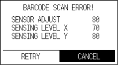
If the start mark is not scanned, the following display is displayed.
Check the print result of start mark and the scanning start position etc.
7. Find the file, and then start cutting.

• If the appropriate files are found, select the desired file.
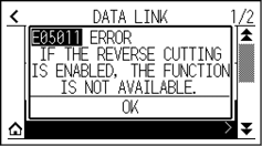
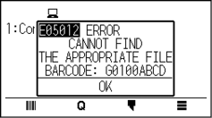
• If the appropriate files is not found, the following screen is displayed.
8. When cutting is completed, it will become READY status.
12.4 Communication Timeout
When the communication is lost during connecting to the data link server, the connection will be canceled after a certain period of time has elapsed.
You can set the time until it is canceled.
Operation
1. Press the [] icon.
2. Press the [LINK].
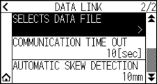
3. Press the [] icon.
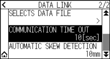
4. Press the [COMMUNICATION TIME OUT].
5. Specify the setting value using the [] [] icon or the [ ] icon.
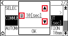
You can set the range between 5 and 60 sec.
6. Confirm the setting and press the [OK].
7. Press the [] icon.
It will return to HOME screen.
12.5 Skew Scanning
When continuous operation is performed, it is possible to set how much skewis allowed by detecting media skew by comparing the start mark positions of the start page and the current page.
For continuous operation, see Instruction manual for each application software.
Operation
1. Press the [] icon.
2. Press the [LINK].
3. Press the [] icon.
4. Press the [AUTOMATIC SKEW DETECTION].
5. Press the setting value you want to use.
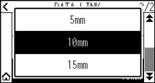
When continuous operation is performed, it is possible to set how much skew is allowed by comparing the start mark position on previous page.
6. Press the [] icon.
It will return to HOME screen.