2.1 Preparation of Cutter Plunger
This section describes the structures and types of the cutter plungers (cutter pens).
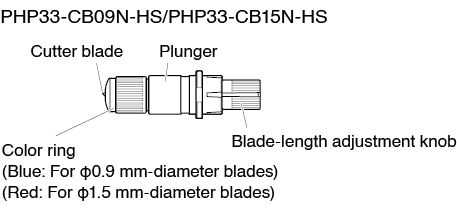
Cutter plunger nomenclature
The plotter cuts using a cutter blade mounted in a plunger. There are two different plungers to suit the diameter of the cutter blade to be mounted (the φ0.9 mm cutter plunger is provided as a standard accessory). Be sure to mount the cutter blade in the corresponding cutter plunger.

To avoid bodily injury, handle cutter blades with care.
Structure of cutter plunger
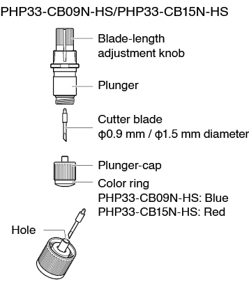
Please fully insert the cutter blade straight into the plunger cap.
If the cutter blade cannot be inserted straight, please insert the cutter blade after pressing the insertion port of the cutter blade several times. If not installed correctly, it may result in damage to the cutter blade or the plotter itself.

Adjusting the blade length
Blade length needs to be adjusted to perform optimal cut.
Perform few test cuts and set the optimal blade length.
• To avoid bodily injury, handle cutter blades with care.
• It may result in damaging the cutter blade or the cutting mat if the blade is extended too much. Make sure the blade length is set less than the thickness of the media.
After adjustment, please always perform “CUT TEST”.

See “2.11 Running Cutting Tests” for cutting tests.
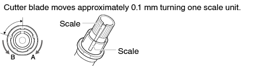
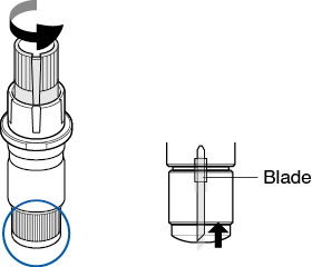
Adjust the blade length by turning the blade-length adjustment knob. Turn the knob in direction "A" to extend the blade, or in direction "B" to retract the blade. When the knob is turned by one scale unit, the blade moves approximately 0.1 mm. One full turn of the knob moves the blade approximately 0.5 mm.

Blade application and features
Select the optimal cutter blade and media to be cut.
Refer to the Cutter Blade Manual.
To avoid bodily injury, handle cutter blades with care.
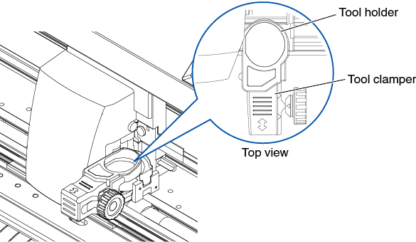
2.2 Attaching a Tool
Attach a tool (cutter plunger, plotter pen) to the plotter.
Attaching a tool
When mounting the tool in the tool holder, please note the following.
• Never touch the tool when the power is turned on or while it is in operation, as it is dangerous.
• When handling the tool holder, be careful not to get injured by the cutter blade.
It is explained here using cutter plunger as an example.
• When using with half cutting and plotter pen, set the seal in Tool Holder (backward), and when using cutting out (perforated cut), set the seal in Tool Holder (forward).
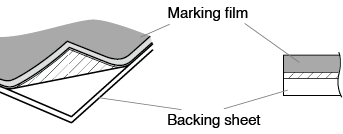
• Half cutting means that only the marking film is cut out, leaving the backing sheet uncut.
• Cutting out means that the media is cut out completely.
• Structure of Marking film
Mounting
1. Loosen the tool holder screw.
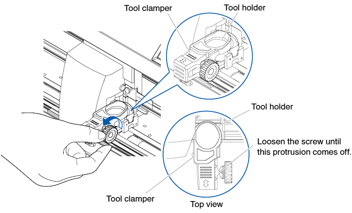
2. Move the tool clamper so that the hole in the tool clamper is aligned with the hole in the tool holder.
3. While pushing up the tool clamper, set the tool in the tool holder.
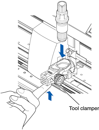
Make sure the tool is set straight into the tool holder.
4. Move the tool clamper.
When using with half cut and pen, push the tool clamper until it touches the backward side firmly.
When using the cutting out (perforated cut), pull the tool clamper until it touches the forward side firmly.
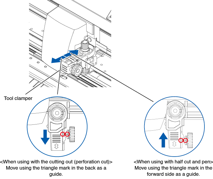
Make sure the tool is set straight into the tool holder.
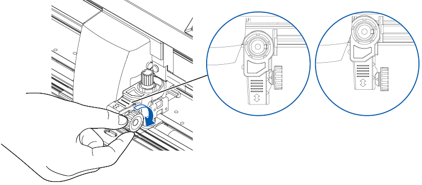
5. Tighten the tool holder screw.
Removing the tool
To remove the tool, loosen the screw until this protrusion mentioned in step 1 of "Attaching a tool" comes off and then remove the tool.
2.3 Loading Media (Paper or Marking Film)
Both roll media and sheet media can be used with the CE8000. Load the media according to the instructions given for each type.
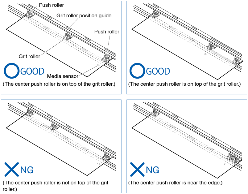
Use the grit roller on the right side of the media (looking from the front) as a guide when setting it in the media sensor. Afterwards, adjust the push roller so that it's lined up with the side of the media.
• Loading Roll Media
• Loading Sheet Media
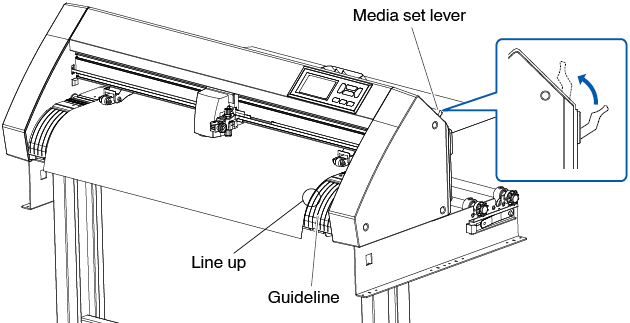
Loading roll media (CE8000-40)
Operation
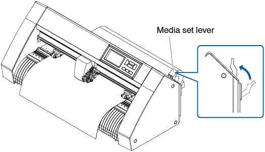
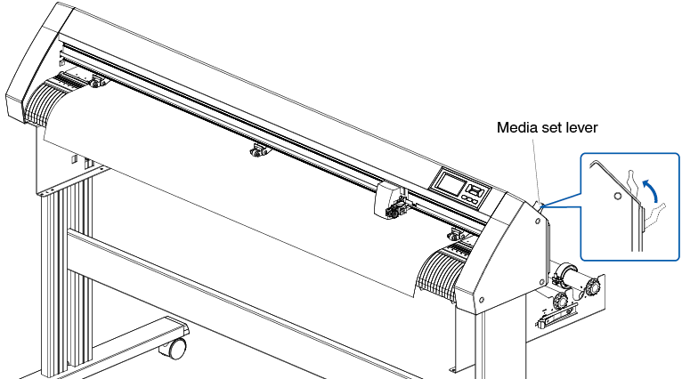
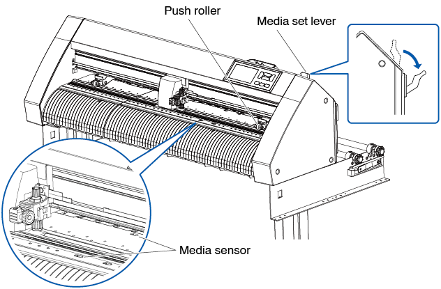
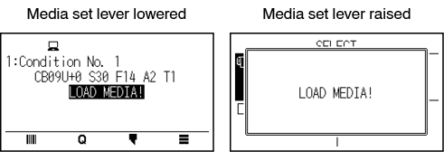
1. Lower the media set lever to raise the push rollers.
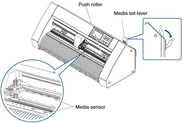
2. Put the roll media on the roll media tray and then push the tip of the roll media forward from the back of the machine. Make sure to pull it so that there is no slackening across the roll media's route.
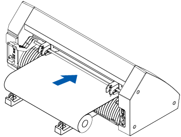
3. Pull the roll media forward until the leading edge of the roll media completely covers the sensor.
If the length you pull out is too long, adjust the length by winding it up on the roll side.
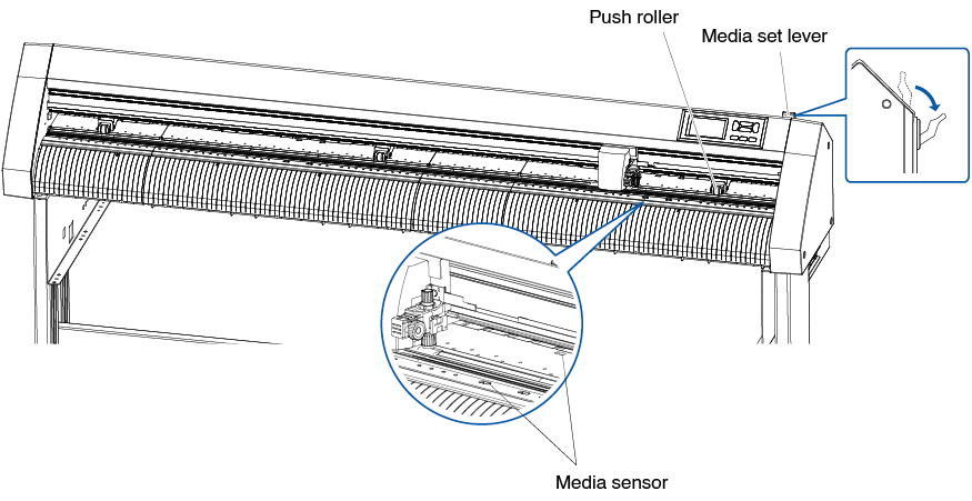
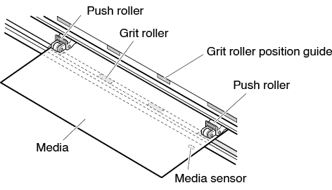
4. Position the media and the push rollers to correspond with the width of the media.
The push rollers push down on either side of the media. Use the grit roller position guide to make sure the push rollers are set on top of the grit rollers.
You can adjust the center push roller's hold-down force.

• The media must always be positioned over the media sensor.
• See “2.4 Aligning the Push Rollers” for the position of the push rollers.
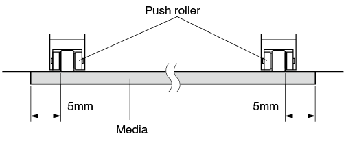
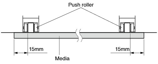
When feeding long media (2 meters or more)
Position the push rollers at least 15 mm inside the edges of the media.
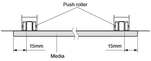
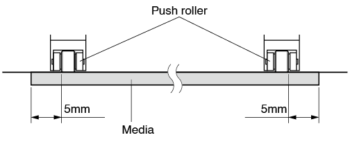
When feeding long media (2 meters or less)
Position the push rollers at least 5 mm inside the edges of the media.
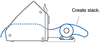
5. Pull the media taut to make sure that there is no slack in the conveyance path, and then raise the media set lever to lower the push rollers.
Create the same amount of slack in the media as will be used for the back of the machine.
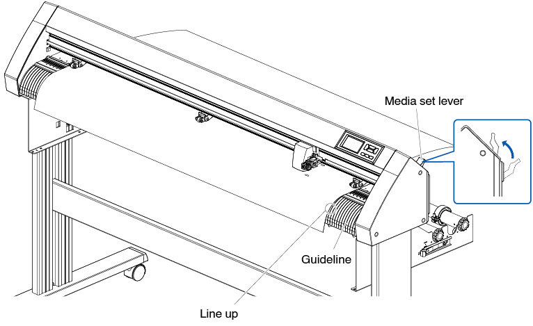
Loading roll media (CE8000-60/130)
This section explains in the CE8000-130.
Operation
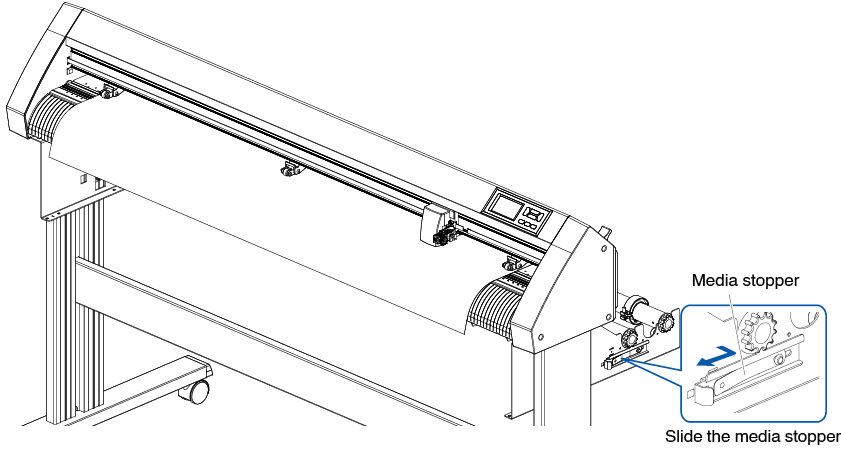
1. Lower the media set lever to raise the push rollers.
2. Set the roll media on top of the stock shaft, and then clip the roll paper with a stopper. Once it’s set, tighten the stopper’s screws.
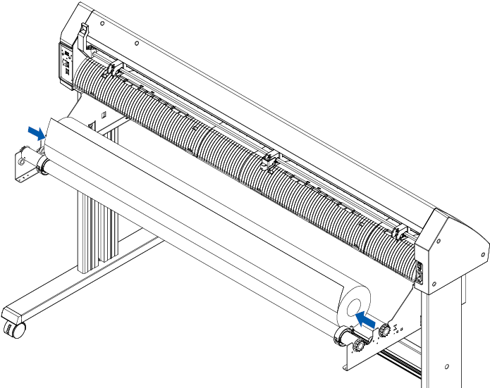
3. Push the tip of the roll media forward from the back of the CE8000. Make sure to pull it so that there is no slackening across the roll media's route.
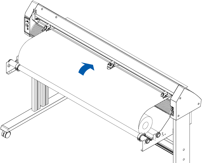
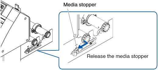
4. Lock the media stopper (Slide it backward.) and pull it out evenly so that the roll paper is straight. Please load so that the roll paper always rests on the media sensor.
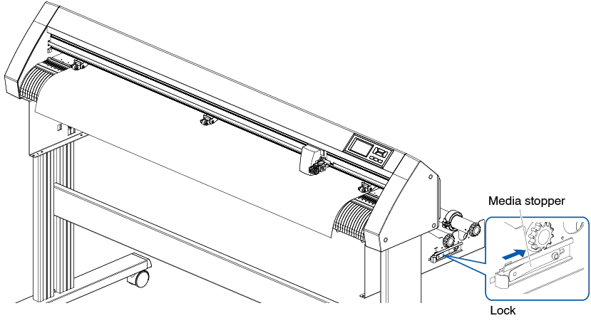
When actually cutting, please release the lock from the media stopper (While pulling the media stopper to the exterior, slide it forward.).
5. Position the media and the push rollers to correspond with the width of the media.
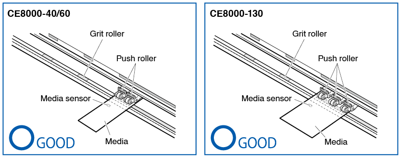
When using CE8000-40/60
The push rollers push down on either side of the media. Use the grit roller position guide to make sure the push rollers are set on top of the grit rollers.
• The media must always be positioned over the media sensor.
• See “2.4 Aligning the Push Rollers” for the position of the push rollers.
When using CE8000-130
Use the 3 push rollers to push down the sides and center of the media. Use the grit roller position guide and make sure the push rollers are on top of the grit rollers.
The central push roller has the push roller’s hold-down force switching function.
• The media must always be positioned over the media sensor.
• See “2.4 Aligning the Push Rollers” for the position of the push rollers and information about push roller hold-down force.
When feeding long media (2 meters or more)
Position the push rollers at least 15 mm inside the edges of the media.
When feeding long media (2 meters or less)
Position the push rollers at least 5 mm inside the edges of the media.
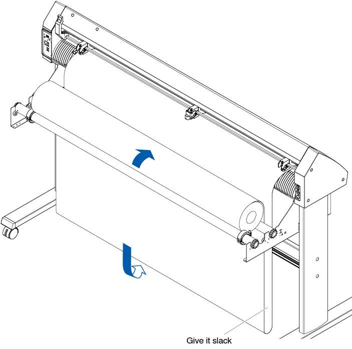
6. Pull the media taut to make sure that there is no slack in the conveyance path, and then raise the media set lever to lower the push rollers.
7. Release the lock from the media stopper (while pulling to the exterior, slide it forward).
8. When the set lever is up (and the media is held down by the push rollers) and the media stopper is unlocked, pull out the roll media and give it slack.
Create the same amount of slack in the media as will be used for the back of the machine.
• Dirt from the floor may stick to the media when giving it slack, so please be careful.
• During continuous operation with roll media, do not make a media slack at the rear of the cutting plotter.
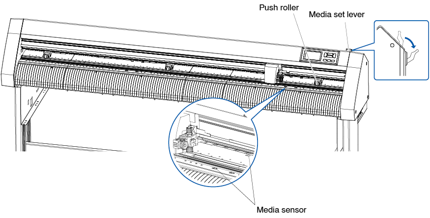
Loading sheet media (CE8000-40/60)
This will be explained in CE8000-60.
Operation
1. Lower the media set lever to raise the push rollers.
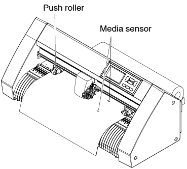
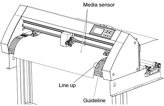
2. Load the sheet media so that the sheet media's right edge lines up with the guideline on the front side.
Make sure that the sheet media completely covers the media sensor.
3. Position the media and the push rollers to correspond with the width of the media.
The push rollers push down on either side of the media. Use the grit roller position guide to make sure the push rollers are set on top of the grit rollers. You can adjust the center push roller's hold-down force.
• The media must be at least 125 mm in length.
• The media must always be positioned over the media sensor.
(For the location of media sensor, see “1.2 Nomenclature”.)
• See “2.4 Aligning the Push Rollers” for information aPush Rollers” for the position of the push rollers and information about push rollers.
4. Load the sheet media so that the sheet media's right edge lines up with the guideline on the front side.
Pull the media taut to make sure that there is no slack in the conveyance path, and then raise the media set lever to lower the push rollers. Set the sheet media so that the paper's edges line up with the guideline on the front side.
Loading sheet media (CE8000-130)
Operation
1. Lower the media set lever to raise the push rollers.
2. Load the sheet media so that the sheet media's right edge lines up with the guideline on the front side.
Make sure that the sheet media completely covers the media sensor.
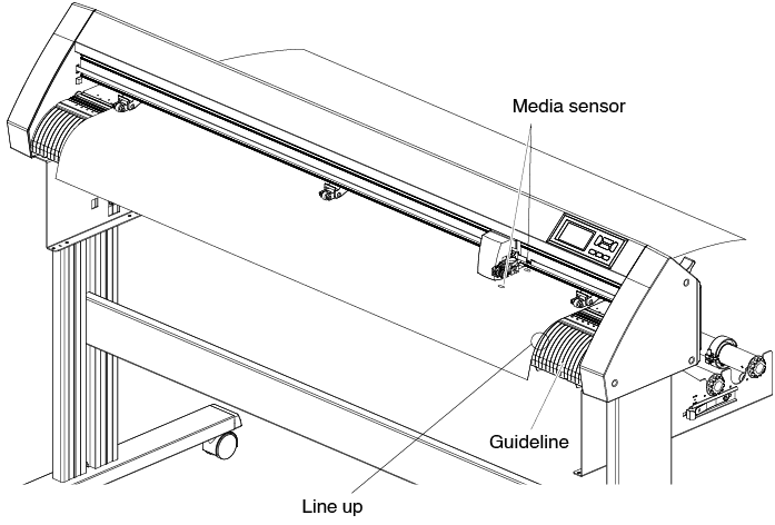
3. Position the media and the push rollers to correspond with the width of the media.
Use the 3 push rollers to push down the sides and center of the media. Use the grit roller position guide and make sure the push rollers are on top of the grit rollers.
• The media must always be positioned over the media sensor.
• See “2.4 Aligning the Push Rollers” for the position of the push rollers and information about push roller hold-down force.
4. Load the sheet media so that the sheet media's right edge lines up with the guideline on the front side.
Pull the roll media taut to make sure that there is no slack in the conveyance path, and then raise the set lever to fix the push roller position and the roll paper.
Carrier Sheet (for Affixing Media for Cutting)
Using the carrier sheet (CR09300-A3) enables designs to be cut out of the following media types:
• Media without a backing sheet
• Media that is smaller than A3 size
• Only CE8000-40/60 supports it.
• The carrier sheet (CR09300-A3) is an optional item.
Usage Precautions
• Be sure to use the carrier sheet when cutting around a printed design on the media to create a cutout.
• The carrier sheet is a reusable adhesive sheet that can be used repeatedly. However, if the carrier sheet become warped or loses its adhesive strength, it can no longer be used. In such cases, please replace it with a new carrier sheet. As a guideline, replace the carrier sheet after cutting 10 sheets. The cutting quality when the same carrier sheet is used for cutting more than 10 sheets is not guaranteed.
• When affixing a media to the carrier sheet, be sure to press down on it firmly to ensure that it does not float up or peel away from the carrier sheet.
• Make sure that media affixed to the carrier sheet has very little curl. A strongly-curled media may cause registration mark reading errors to occur, and it may get caught up in the pen carriage.
• Affix only Graphtec-specified media to the carrier sheet. If using commercially-available inkjet media, please note that media that is coated on both sides cannot be used. If the media is coated on one side only, affix the non-coated side to the carrier sheet. If the coated side is affixed, the carrier sheet’s adhesive strength will be weakened and may make the carrier sheet unusable.
• If very smooth paper (paper that does not feel rough to the touch) is affixed to the carrier sheet, it will tend to curl up when removed from the carrier sheet. Please be careful when using it.
• When removing a media from the carrier sheet after cutting it, be sure to remove it slowly and carefully.
• The adhesive surface of the carrier sheet absorbs moisture easily. To prevent this occurring, do not remove the carrier sheet from its package until just before use.
• After use, reattach the separator that was removed from the adhesive surface prior to use, and then return the carrier sheet to its package for storage.
• For optimum storage, avoid locations where there is high humidity or where the package will be exposed to direct sunlight.
• There may be cases in which thin materials such as copy paper can no longer be peeled or torn.
Loading the Media
How to load a media with a width of less than 297mm
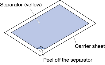
1. Peel off the separator (yellow) from the carrier sheet to expose the adhesive surface. (Do not discard the separator, as it will be used again when the carrier sheet is returned to its package for storage.)
2. Affix the media for cutting to the adhesive surface of the carrier sheet, making sure that the edges of the media are parallel with those of the carrier sheet.
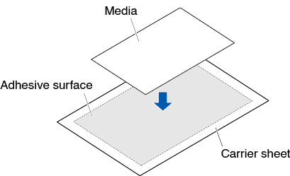
• Do not use media that is smaller than postcard size.
• When affixing the media, take care not to cause any air bubbles or creases.
Effective Cutting Area
1. The effective cutting area on the carrier sheet is shown in the diagram below. When loading a media that is smaller than A3 size in the cutting plotter, be sure to affix it within the cutting area (the adhesive surface). Moreover, make sure that the edges of the media are parallel with the edges of the carrier sheet.
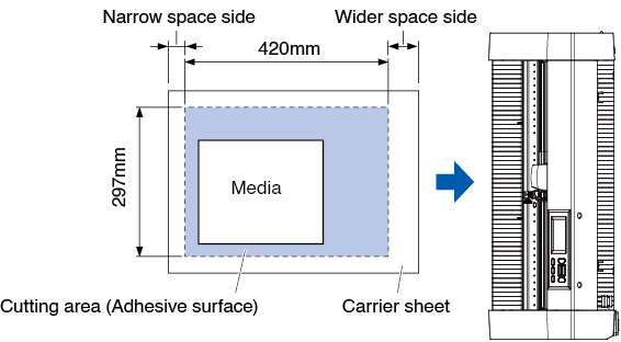
• The plotter recognizes the width of the carrier sheet as the cutting area.
Be sure to load a media that is the same size as the media setting that was made in the application software
• Be sWhen affixing the media, take care not to cause any air bubbles or creases.peration.
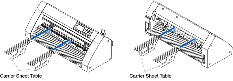
Mounting the Carrier Sheet Table
1. Mount the carrier sheet table to the front and back of the cutting plotter.
Insert the projection under the carrier sheet table into the dent part.
For CE8000-40, insert the front side into the first and third grooves from the right.Align the back side in the same position as the front side.
For CE8000-60, insert the front side into the second and fourth grooves from the right. Align the back side in the same position as the front side.
* The carrier sheet table (OPH-A45) is an optional item.
Setting method of carrier sheet (Carrier Sheet Table)
1. When setting the carrier sheet, insert it so that the narrowest margin (transparent part) of the carrier sheet is at the top, and make sure that the carrier sheet is in front of the cutting plotter as shown in the figure.
Make sure that the carrier sheet does not come out behind the cutting plotter.
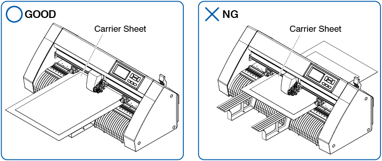
Set it so that the right edge of the carrier sheet aligns with the guidelines on the front guide.
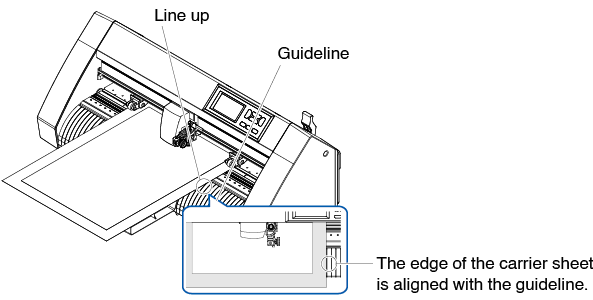
2. When the set lever is raised, the push roller lowers and the carrier sheet is fixed.
2.4 Aligning the Push Rollers
This section describes how to alignment of the push rollers.
Aligning the push roller
Position the left and right push rollers to correspond with the width of the media. Adjust the push rollers so that they are positioned above both the media and the grit rollers.
Positioning the push rollers within the grit roller position guides ensures that they are above the grit rollers.
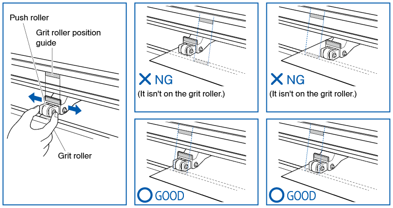
To move the push rollers, the media set lever must be in the lowered position.
If a [REALIGN PUSH ROLLERS] message appears after setting the media and raising the media set lever, it means the right push roller is not on the right grit roller, or that the left or center push roller is not on the proper grit roller.
Make sure everything is set correctly.
When feeding long media (2 meters or more)
Position the push rollers at least 15 mm inside the edges of the media.

When feeding long media (2 meters or less)
Position the push rollers at least 5 mm inside the edges of the media.
When narrow media is used
Make sure that all push rollers are on the long right grit roller. Use the left side of the grit roller as a starting point and then set the push rollers so that they're on both sides of the media.
The width of media that can be set is 50 mm or more for CE8000-40/60 and 85 mm or more for CE8000-130.
* For CE8000-130, when setting all push rollers to the rightmost grit roller (wide), set the hold-down force of the center push roller to Low (OFF).
• The media must be at least 125 mm in length in media feed direction.
• The media must always be positioned over the media sensor.
Changing the hold-down force
The CE8000-130 requires the push roller hold-down force to be set based on the media's width and material type in order to keep the media in place.
Switching
1. Lower the media set lever and raise the push roller.
2. Switch the hold-down force of the central push roller to Medium or Low (OFF) using the hold-down force switching lever at the rear of the push roller.
3. Raise the hold-down force switching lever to set it to the Medium state, and lower it to set it to Low (OFF).
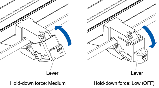
• The hold-down force of the push rollers at both ends cannot be changed.
• When switching the hold-down force, be sure to lower the set lever before switching.
• Set the hold-down force to be Low (OFF) when cutting by pressing the center of ultra-thin film such as car film.
• Please change the hold-down force depending on the type of media.
• When using the push roller with the hold-down force set to Low (OFF), set “Enabling/Disabling the push roller sensors (Enabling/Disabling the push roller sensors)” to [INSIDE DISABLED]. And then move the push roller to a position where there is no grit roller.
2.5 About the Default Screen
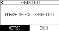
The Initial Setup Screen appears only when powering up the machine for the first time after purchase. Here, you can set the “Display language”, “LENGTH UNIT” and “Wireless LAN”.
Also, after setup, you can select the menu even from the READY status.
See "2.6 Connecting to the Power" for turning on the power.
Operation
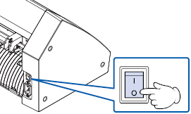
1. Once the machine is powered on (with the " | " switch) a message will be displayed after the firmware version is displayed.

2. Press the language you want to use.
3. Press the unit you want to use.
4. Select whether to make the wireless LAN settings.
Press [YES] to proceed to the access point setting.
For information on how to set up wireless LAN, see "9.2 Connecting via wireless LAN".
Press [NO] to go to the HOME screen.

This screen will not be displayed if wireless LAN module is not installed.
5. Once the settings are confirmed, the HOME screen will be displayed.
2.6 Connecting to the Power
Turning on the power of the plotter.
Operation
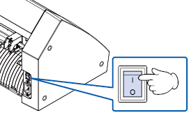
1. Check that the power switch is turned off. (the " " side is pressed down)
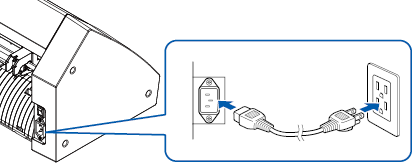
2. Connect one end of the provided power cord to the CE8000 AC line inlet and the other end to an electrical socket of the rated supply voltage.
3. Turn on the CE8000 by pressing the "|" side of the switch. LCD on the control panel is lit.
When turning the power off, wait over 20 seconds before turning it on again, otherwise problems may occur with the display.
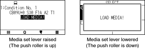
4. If media has not been loaded, the firmware version number is displayed, followed by a prompt to load media.
The Default Screen will appear after purchasing the machine. See “2.5 About the Default Screen” for more information.
2.7 How to Use Control Panel
This section explains the function on the control panel.
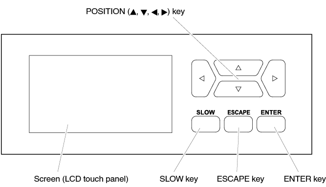
Operation key
POSITION ( ,
,  ,
,  ,
,  ) key
) key
Adjusts various settings, selects numerical value changes, moves the cursor, and changes the positions in the MENU screen.
SLOW key
When pressing the POSITION key at the same time, the tool carriage moves slowly.
When the [SLOW] key is pressed in the READY screen, the current cutting/plotting area and the position of tool carriage are displayed.
If you want to change the cutting conditions while plotting/cutting, press the [SLOW] key while plotting/cutting.
ESCAPE key
Cancels the setting change and then returns to the previous screen. Returns to the previous screen in the MENU screen.
If you want to temporarily stop plotting/cutting, press the [ESCAPE] key during plotting/cutting.
ENTER key
Saves the settings, and then returns to the setting screen in various function or CONDITION setting screen of the MENU screen.
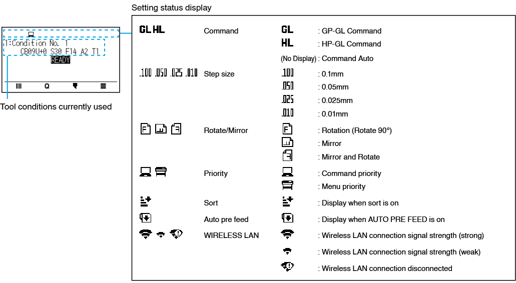
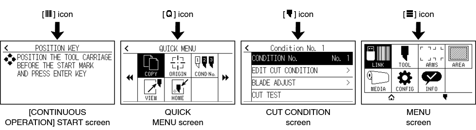
Control panel screens
Information according to the current situation is displayed on the control panel screen.
How to operate the control panel screen
You can operate this plotter using either the touch panel or operation keys.
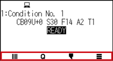
How to operate the HOME screen (READY state)
When using the touch panel
Use the [ ], [
], [ ], [
], [ ] and [
 ] icons.
When using the operation keys
Hold down the [ENTER] key and press the POSITION (, ) keys to select the [], [], [[] or [] icon.
Release the [ENTER] key to move to each menu.
There are screens other than the Home screen that have the above icons.
Move to each menu by pressing the icon.
How to operate the MENU screen
When using the touch panel
Press the icon.
When using operation keys
Select the icon using the POSITION (,  , ,
, ,  ) keys. Press the [ENTER] key.
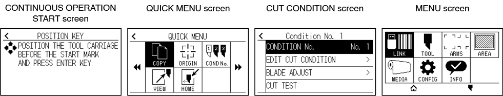
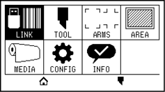
Contents to be operated from the [ ] icon - Menu screen
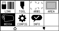
The contents that can be operated and set from the MENU screen are as follows.
LINK
Performs operations necessary for output such as data links.
TOOL
Sets the conditions related to tool operation.
ARMS
Performs settings and operations related to alignment of tools and media, such as automatic registration mark scanning using ARMS.
AREA
Sets the cutting plotting area, scale, rotation and mirror, etc.
MEDIA
Sets the conditions related to media.
CONFIG
Sets the basic operating conditions of this plotter, such as the display language, length unit and sensor.
Sets the conditions related to the interface with the connected computer.
INFO
Performs operations necessary for maintenance, such as diagnostic test and exporting condition setting lists.
[ ] Used to close the menu screen and to return to the home screen.
[] Used to close the menu screen and to move to the condition screen.
For a list of setting items, see "A.4 Menu Tree."
Contents to be operated from the [ ] icon - CUT CONDITION screen
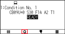
Set the tool conditions on the CUT CONDITION screen.
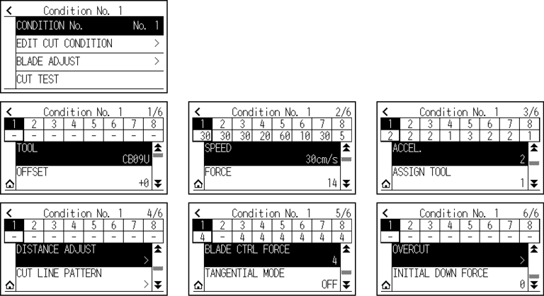
Tool conditions can be saved by assigning condition numbers 1 to 8 to each different setting.
[] Used to close the condition screen and to return to the HOME screen.
[ ] Used to close the CUT CONDITION screen and to return to the previous screen.
For "Tool Conditions", see "2.10 Setting the Tool Condition".
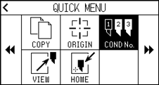
Contents to be operated from the [ ] icon - QUICK MENU screen
The contents that can be operated and set from the QUICK MENU screen are as follows.
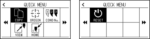
COPY
Copies and outputs data in buffer memory.
ORIGIN
Sets the current tool position as the origin point (cutting point).
COND No.
Changes the cutting condition number.
VIEW
The tool carriage is moved away.
HOME
The tool carriage moves to the cutting origin position.
RESET
Returns to the state immediately after power-on.
Contents to be operated from the [ ] icon - [CONTINUOUS OPERATION] START screen
In the [CONTINUOUS OPERATION] START screen, the screen for starting continuous operation is displayed.
Same operation as when [] - [LINK] - [CONTINUOUS OPERATION] are selected.
How to operate the setting screen
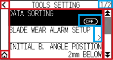
This section describes using the [TOOLS SETTING] screen as an example.
When using the touch panel
• Go back one level up: Press [ ].
].
• Return to the HOME screen: Press [ ].
].
• Return to previous page: Press [ ].
].
• Go to the next page: Press [ ].
].
• Select of setting items: Press each setting item.
When using operation keys
• Go back one level up: Press the [ESCAPE] key or POSITION () key.
• Return to the HOME screen: Hold down the [ENTER] key and press the POSITION () key, then select the [] icon. Release the [ENTER] key to move to the HOME screen.
• Return to the previous page: Hold down the [SLOW] key and press the POSITION () key.
• Go to the next page: Press the [SLOW] key.
• Selecting a setting item: Press the POSITION (, ) key to select the setting item, then press the [ENTER] key.
• “1/2” at the top right of the screen is the page number.
• Setting items that display [OFF] or [ON] will be toggled between [OFF] and [ON] each time you press the setting item (press the [ENTER] key).
• Setting items with a [ ] icon have menus below them.
How to operate options
This section describes using the [TOOLS SETTING] - [INITIAL B. ANGLE POSITION] as an example.
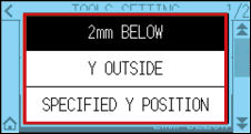
When using the touch panel
Press the setting item.
When using operation keys
Select the setting item using the POSITION (, ) keys. Press the [ENTER] key.
You can cancel the settings by pressing outside the option popup screen or pressing the [ESCAPE] key.
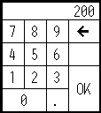
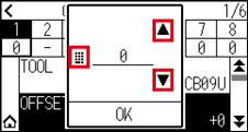
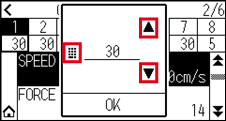
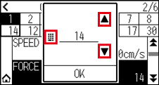
How to operate numerical input
This section describes using the [MEDIA SETTING] - [PAGE LENGTH] as an example.
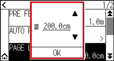
When using the touch panel
Press the [] [] icon or the [ ] icon.
When you have finished entering the numerical values, press the [OK].
• Press the [ ] icon to display the numeric keypad.
Press the number you want to enter, then press the [OK].
• You can cancel the settings by pressing the numeric keypad outside the pop-up screen.
When using operation keys
Press the POSITION (, ) keys or the [SLOW] key.
When you have finished entering the numbers, press the [ENTER] key.
• Press the [SLOW] key to display the numeric keypad.
Select the number you want to enter using the POSITION ( ,
,  ,
,  ,
,  ) keys and press the [ENTER] key.
When you have finished entering the numbers, select the [OK] using the POSITION (, , , ) keys and press the [ENTER] key.
• Press the [ESCAPE] key to cancel the settings.
2.8 Setting Feeding Method
Feeding method for the loaded media is set.
Operation
1. If you have already loaded the media, the MEDIA TYPE menu appears. Select the media type to suit the loaded media.
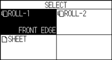
Check that the media stopper is unlocked (CE8000-60/CE8000-130) and then select a media type on the MEDIA SELECT screen.
* The figure below is CE8000-130.
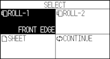
Before doing the media set selection, make sure to release the media lock.
If you raise or lower the media set lever again after loading the media, [Continue] will be added and you For information on how to install the tool, see “2.2 Attaching a Tool”.can select the previous setting.
If you use the same media without changing its position, the cutting area, pen position and origin point before lowering the media set lever will continue. If you reload the media without changing the media width, you can omit the media width detection operation.
 .
.
[ROLL-1 FRONT EDGE]
Select this when you have loaded a roll media and you wish to start cutting or plotting from the leading edge.
The width and leading edge of the roll media are detected.
[ROLL-2 CURRENT POSITION]
Select this when you have loaded a roll media and you wish to start cutting or plotting from a point beyond the leading edge.
Only the width of the roll media is detected.
[SHEET]
Select this when a sheet media has been loaded.
The width, leading edge, and trailing edge of the sheet media are detected.
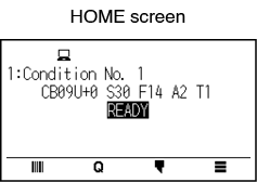
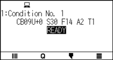
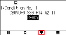
2. After the media is detected, the plotter is ready to receive data for cutting or plotting.
This status is called "READY status" of the default screen.
When setting is finished, the tool carriage's location will become the initial point.
• When loading the media, the fan suction operates to assist in loading the media.
If you want to turn off this function, please refer to “10.3 Related to Plotter Environment”.
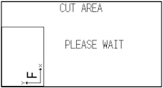
• The following screen will be displayed while media is being detected.
2.9 Pre Feed of Media (Paper or Marking Film)
The PRE FEED function is used to prevent the loaded media from slipping by automatically advancing the media the specified length and imprinting it with grit roller marks. This function can also be used to acclimate long media lengths to the operating environment in order to minimize media expansion and contraction, and to ensure stable media feed operations.
When performing plotting/cutting longer than 2 m in CE8000-60/130, be sure to use a basket (option).
Operation
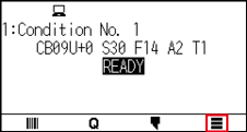
1. Press the [] icon.
2. Press the [MEDIA] icon.
3. Press the [PRE FEED].
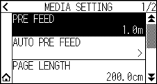
4. Specify the setting value using the [] [] icon or the [] icon.
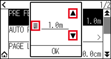
You can set the range between 0.5 m and 50 m.
5. Confirm the setting and press the [OK].
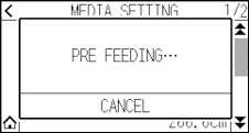
Pre feed will start.
• When Pre Feed of Media is performed, the following screen is displayed.
To cancel the Pre Feed, press the [CANCEL].
• If you select “SHEET” in the media feeding, the Pre Feed will not be performed.
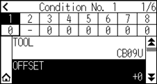
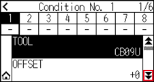
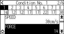
2.10 Selecting Tool Condition
Set the “TOOL CONDITION (CUT CONDITION) No.”, “TOOL”, “OFFSET”, “SPEED”, “FORCE”, and “ACCEL (ACCELERATION)”.
You can switch to the settings for each of the 8 preset media types.
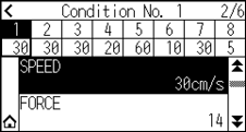
Selecting the TOOL CONDITION number (Condition No.)
This section explains how to select the TOOL CONDITION number (Condition No.).
Operation: Operation with the [] icon
1. Press the [] icon.

2. Press the [CONDITION No.].
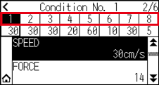
3. Use the [] and [] icons to display the tool condition number you want to use.
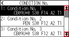
4. Press the tool condition number you want to use.
5. Press the [] icon.
 It will return to HOME screen.
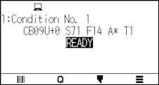
Operation: Operation with the [] icon
1. Press the [] icon.
2. Press the [COND No.] icon.
3. Use the [] and [] icons to display the tool condition number you want to use.
4. Press the tool condition number you want to use.
It will return to HOME screen.
Setting the tool condition
This section describes how to make the tool, speed, force and acceleration settings.
Before cutting media, the following four cutter-pen conditions must be specified.
• FORCE
• SPEED
• ACCELERATION
• OFFSET
It may result to damaging the cutter blade or the cutting mat if the blade is extended too much. Make sure the blade length is set less than the thickness of the media.
Tool Conditions (Cutter Blade) for Each Media Type
See the Cutter Blade Manual.
Blade Part Nos., Displayed Blade Types, and CUTTER OFFSET Values
See the Cutter Blade Manual.
Reference Pen Conditions for Plotting Pen
|
Pen type |
Cut/Force |
Speed (cm/s) |
Acceleration |
|
Water-based fiber-tip pen |
10 to 12 |
30 |
2 |
|
Ballpoint pen |
12 to 31 |
30 |
2 |
To prolong the pen life, set the FORCE to the lowest setting, and set the SPEED after checking to confirm that there are no faint lines or other problems during plotting.
How to Improve Weed ability
We recommend that you observe the following points to improve the weed ability of media.
• Select the correct blade for the application.
See the Cutter Blade Manual.
• Use blades that are not worn.
If the blade is worn, it will not cleanly and the cut results will be difficult to weed.
• Adjust the blade-length and FORCE settings until only traces of the blade are left on the backing sheet.
Specify a FORCE value that is as low as possible, but that still leaves faint traces on the backing sheet.
• Set the SPEED and ACCELERATION values as low as possible.
• Weed the cut results right after cutting has been completed.
If time is allowed to elapse, adhesive along the cut edges will cause the edges to stick together.
• Select media with good weldability.
Recommended film types: 3M Scotchcal Series 7725.
Weeding refers to the removal of un wanted areas of vinyl from the background after the media has been cut.
• Finish will become coarser, but the cut time is decreased when the settings for the speed and acceleration is set higher.
Especially with the large media, good cut quality might not be achieved by rumbling media. Decrease the values for the speed and acceleration settings in that case.
• Finish will become good, but the cut time will increase when the settings for the speed and acceleration is set smaller.
• If you try to set speed 64 and acceleration 3 at the same time on CE8000-40/60, the acceleration will be displayed as “ * “.
In this case, the speed and acceleration settings will operate with automatically calculated values.
• If the acceleration is 2 for CE8000-130, the speed cannot be set to 65 or higher (65, 70, 71).
In this case, the acceleration will be displayed as “ * “ and the speed and acceleration settings will operate with automatically calculated values.
Setting the tool
Set the type value of the tool that is used.
Operation
1. Press the [] icon.
2. Press the [EDIT CUT CONDITION].
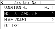
3. Press the tool condition number (1 to 8) you want to set.
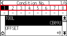
4. Press the [TOOL].
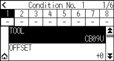
5. Use the [] and [] icons to display the tools you want to use.
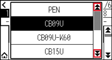
6. Press the tool you want to use.
The tools that you can select are [PEN], [CB09U], [CB09U-K60], [CB15U] and [OTHER].
7. Press the [] icon.
It will return to HOME screen.
Tool offset setting
This section describes how to set the tool offset you want to use.
Operation
1. Press the [] icon.
2. Press the [EDIT CUT CONDITION].
3. Press the tool condition number (1 to 8) you want to set.
4. Press the [OFFSET].
5. Specify the setting value using the [] [ ] icon or the [] icon.
• What is Offset
It will adjust the difference between the tip of the blade in the plunger and the center of the plunger. There are standard adjustment values for each cutter blades. Fine adjustment will be made to those standard values here. (Adjustment will be made with standard value as 0.)
It is not necessary to set the offset if “PEN”, was selected in the tool settings. (not displayed)
• Guideline to Set Offset
See the Cutter Blade Manual
• The range that can be set with the tool other than [OTHER] is [-5] to [+5].
The range that can be set in [OTHER] is [+1] to [+45].
6. Confirm the setting and press the [OK].
7. Press the [] icon.
It will return to HOME screen.
Setting the speed
This section explains how to set the speed to be used.
Operation
1. Press the [] icon.
2. Press the [EDIT CUT CONDITION].
3. Press the [] icon.
4. Press the tool condition number (1 to 8) you want to set.
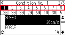
5. Press the [SPEED].
6. Specify the setting value using the [] [] icon or the [] icon.
The settable range varies depending on the model.
CE8000-40: 1 to10 (in 1 cm/s increment), 10 to 60 (in 5 cm/s increment), 64
CE8000-60: 1 to10 (in 1 cm/s increment), 10 to 60 (in 5 cm/s increment), 64
CE8000-130: 1 to10 (in 1 cm/s increment), 10 to 70 (in 5 cm/s increment), 71
7. Confirm the setting and press the [OK].
8. Press the [] icon.
It will return to HOME screen.
Setting the force
This section explains how to set the force to be used.
Operation
1. Press the [] icon.
2. Press the [EDIT CUT CONDITION].
3. Press the [] icon.
4. Press the tool condition number (1 to 8) you want to set.
5. Press the [FORCE].
6. Specify the setting value using the [] [] icon or the [] icon.
You can set the range between 1 and 38.
7. Confirm the setting and press the [OK].
8. Press the [] icon.
It will return to HOME screen.
Setting the acceleration
This section explains how to set the acceleration to be used.
Operation
1. Press the [] icon.
2. Press the [EDIT CUT CONDITION].
3. Press the [] icon twice.
4. Press the tool condition number (1 to 8) you want to set.
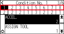
5. Press the [ACCEL. (Acceleration)].
6. Specify the setting value using the [] [] icon or the [] icon.
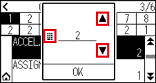
The settable range varies depending on the model.
CE8000-40: 1 to 3
CE8000-60: 1 to 3
CE8000-130: 1 to 2
7. Confirm the setting and press the [OK].
8. Press the [] icon.
It will return to HOME screen.
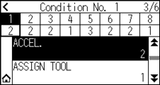
Setting tool No.
This section explains how to assign the tool number to use.
Operation
1. Press the [] icon.
2. Press the [EDIT CUT CONDITION].
3. Press the [] icon twice.
4. Press the tool condition number (1 to 8) you want to set.
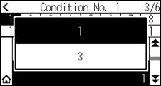
5. Press the [ASSIGN TOOL].
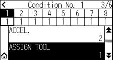
You can set to 1 or 3.
6. Press the tool number you want to use.
7. Press the [] icon.
It will return to HOME screen.
• Tool number and installed position
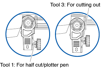
Tool 1: When using a tool installed behind the tool holder
Tool 3: When using a tool installed in front of the tool holder
• For information on how to install the tool, see “2.2 Attaching a Tool”.
Adjust the blade length manually
Optimal cut is not achieved unless the blade length is adjusted in accordance to the used media and the cutter blade.
Perform further adjustment by performing cutting test after adjusting the blade length manually.
• To avoid bodily injury, handle cutter blades with care.
• It may result to damaging the cutter blade or the cutting mat if the blade is extended too much. Make sure the blade length is set less than the thickness of the media.
See “2.11 Running Cutting Tests” for cutting tests.
Operation
1. Align the blade tip to the tip of the cutter pen, and make it touch the surface of the media.
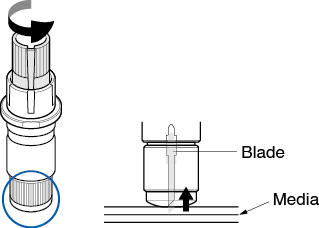
2. Extend the blade little by little to the thickness of the media.
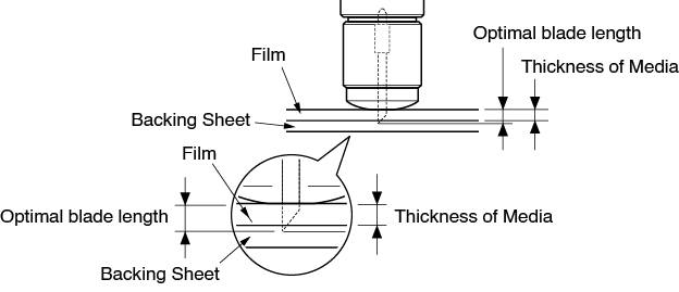
Optimal blade length is less than the thickness of film and backing sheet combined, but more than the thickness of the film.
Try cutting the film, and adjust so there is slight cutting on the backing sheet. If the backing sheet gets cut completely, reduce the blade length, and if the film does not get cut completely, increase the blade length.
• Blade length can be changed by spinning the adjustor on the blade. Spinning it in the A direction pushes it out, while spinning it in the B direction pulls it in. One scale unit is equal to 0.1 mm.
2.11 Running Cutting Tests
Test cutting can be performed after making the tool, speed, force, and acceleration settings to ensure that the selected cutting conditions actually produce the desired cutting results. Check how far the blade cuts into the media and how the corners are being cut. If the cutting results are not satisfactory, adjust the various settings and repeat the test cutting until the optimal settings are achieved.
Cutting test
Here, you can either cut one test pattern based on the current values, or do three tests with ±1 values added. Select the method that suits your situation and make a cutting test.
To make 1 cut with set value
Operation
1. Load the actual media you want to cut.
2. Press the [] icon.
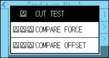
3. Press the [CUT TEST].
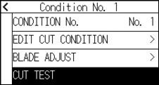
4. Press the [CUT TEST].
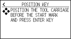
5. Press the POSITION (, , , ) keys to move the tool carriage to the location you wish to perform the test
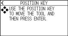
Pressing the POSITION and [SLOW] keys at the same time will move the tool carriage slower.
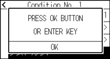
6. Press the [ENTER] key.
 1 cut test pattern is cut.
When the [ENTER] key is pressed, the tool carriage will start moving, so take care not to get injured by the cutter blade.
7. Check the test cut results.
8. Press the [OK] or [ENTER] key.
9. Press any position outside the option (blue part).
10. Press the [] icon.
It will return to HOME screen.
To make 3 cuts with set value and ±1 of set value
Operation
1. Load the actual media you want to cut.
2. Press the [] icon.
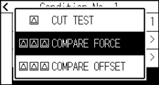
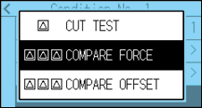
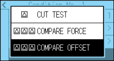
3. Press the [CUT TEST].
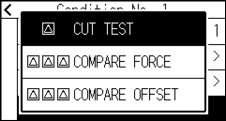
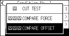
4. If you want to perform a cutting force test, press the [COMPARE FORCE].
If you want to perform an offset test, press the [COMPARE OFFSET].
5. Press the POSITION (, , , ) keys to move the tool carriage to the location you wish to perform the test cutting.
Pressing the POSITION and [SLOW] keys at the same time will move the tool carriage slower.
6. Press the [ENTER] key.
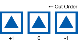
If you perform [COMPARE FORCE], three cut test patterns will be cut one with the cutting force increased or decreased by 1 based on the current cutting force.
If you perform [COMPARE OFFSET], three cut test patterns will be cut one with the offset value increased or decreased by 1 based on the current offset value.
When the [ENTER] key is pressed, the tool carriage will start moving, so take care not to get injured by the cutter blade.
The cut test pattern has the cut order and cut force or offset increase/decrease value as shown in the figure below.
7. Check the test cut results.
8. Press the [OK] or [ENTER] key.
9. Press any position outside the option (blue part).
10. Press the [] icon.
It will return to HOME screen.
Confirm the results of the cutting test
Confirm the cutting test results, and adjust to optimal setting. Repeat cutting test and adjustment until optimal cut is achieved.
Adjustment of Offset
Check the corners of the triangles and rectangles. See "Setting the Tool Condition" and adjust the offset value if the corner is not cut or if it is cut too much.
How to check offset
Check if the offset value is set correctly by following.
 Not enough adjustment value. Increase the offset value.
 Optimal offset value.
 Too much adjustment value. Decrease the offset value.
Adjustment for Half Cutting
Peel off the triangle area, and adjust so it cuts slightly into the backing sheet.
If the backing sheet has been cut through, either the FORCE setting is too high or the cutter-blade tip is extended too far. If the backing sheet shows only a few traces of the cutter blade, either the FORCE setting is too low or the cutter blade tip is not sufficiently extended.
See “Adjusting the Blade Length” and “Setting the Force” and adjust the settings.
Adjustment for cutting out
Adjust so the media is completely cut out.
If the media is not completely cut, either the FORCE setting is too low or the cutter blade tip is not sufficiently extended.
See "Adjusting the Blade Length" and "Setting the Force" and adjust the settings.
Adjustment when using plotting pen
Adjust the FORCE so there will be no faint lines. To prolong the pen life, set the FORCE to the lowest setting without any faint lines. See "Setting the Force" or setting the FORCE.
Adjust the blade length (Automatic Height Adjust)
Test cutting must be performed several times in order to confirm the optimal blade length setting. However, if the blade length adjustment function is used, the optimal length can be easily set.
The measured height is a guideline only. After attempting to cut the actual media, please adjust blade length accurately.
For more accurate adjustment, please use a Loupe (PM-CT-001: option).
Operation
1. Load the media for test cutting in the plotter.
2. Press the POSITION (, , , ) keys to move the tool carriage to the location you wish to perform the blade length adjustment.
3. Press the [] icon on the HOME screen.
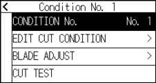
4. Press the [BLADE ADJUST].
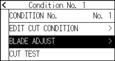
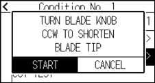
5. As instructed, turn the blade length adjustment knob to the left to fully retract the blade.
See “2.1 Preparation of Cutter Plunger” for blade length adjustment knob.
6. Set the cutter plunger in backward of Tool Holder.
Adjustment is only possible for the cutter pen set in backward of Tool Holder.
It does not apply to forward of Tool Holder.
7. Press the [START]. The tool moves down/up and measures the height.
8. Press the [TARGET].
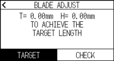
9. Specify the target value using the [] [] icon or the [] icon.
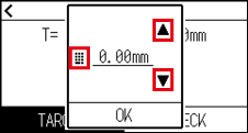
10. Confirm the setting and press the [OK].
11. Press the [CHECK].
The height is calculated by moving the tool up and down.
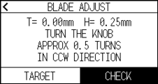
“T” is the target value of the blade length, and “H” is the current blade height (amount).
Turning the blade-length adjustment knob displays the number of turns and direction.
12. Turn the blade-length adjustment knob and adjust the cutter blade length.
Current blade length is displayed by pressing the [CHECK], so adjust the blade length until it matches the thickness of the media.
Depending on the media type, the blade might sink in to the media, making accurate measurement impossible.
13. Press the [] icon twice.
It will return to HOME screen.
2.12 Displaying Cutting Area
Check the cutting area.
Operation
1. Press the [SLOW] key in the HOME screen.
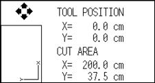
The [TOOL POSITION] indicates the current tool position in the cutting area.
2. Release the [SLOW] key.
It will return to HOME screen.