Chapter 6: Manual Position Adjust
This chapter describes how to manually align media and tool positions.
6.1 Outline of Manual Position Adjust
With manual position adjust, tilt of the axes are adjusted using the 2 POINTS, 3 POINTS, or 4 POINTS adjustment marks (grits or registration marks) as a standard. The distance between each point can also be entered to adjust the distance.
Move the tip of each tool to the appropriate point.
Use the media with prints (grits or registration marks) necessary to get XY axes and origin point.

If you want to perform accurately matching up points, please use the ARMS function.
Setting mark scan mode and number of adjustment marks
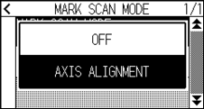
To perform the AXIS ALIGNMENT, set the MARK SCAN MODE to "AXIS ALIGNMENT".
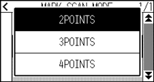
Select the number of the registration marks (adjustment marks) from 2 POINTS, 3 POINTS, or 4 POINTS when the MARK SCAN MODE is set to "AXIS ALIGNMENT". Position of each adjustment marks are as following.
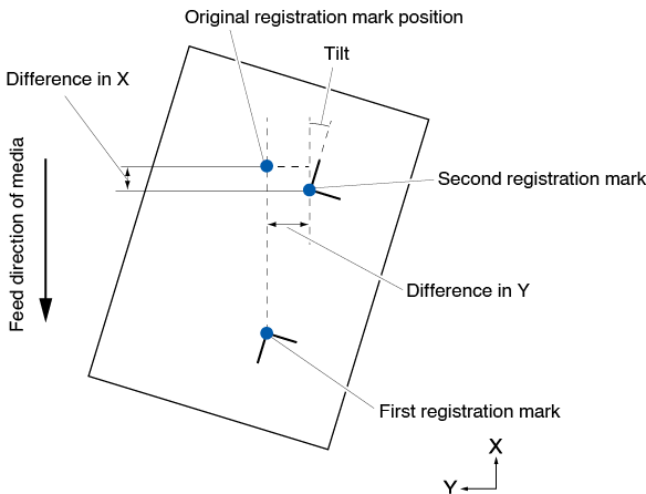
Adjust with 2 POINTS
2 POINTS adjustment will scan 2 registration marks aligned in the media transportation direction, where the adjustment is done measuring the tilting of the axis and the distance between the registration marks. This adjustment is 1-axis adjustment (tilt adjustment).
If the loaded media is tilted as shown below, position of the scanned registration mark is shifted from the position where it should be. Tilt and distance can be adjusted by comparing these coordinate values.
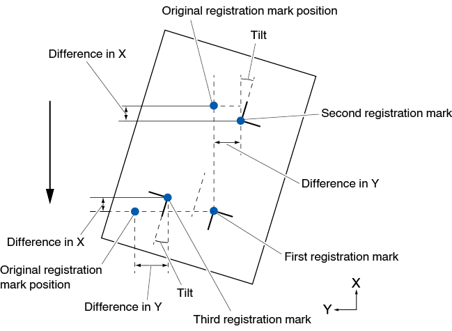
Adjust with 3 POINTS
3 POINTS adjustment will scan 3 registration marks as shown below, where the adjustment is done measuring the tilting of the X and Y axes and the distance between the registration marks (horizontal and vertical directions).This adjustment is called 2-axis adjustment (tilt adjustment).
If the loaded media is tilted as shown below, position of the scanned registration mark is shifted from the position where it should be. Tilt and distance can be adjusted by comparing these coordinate values.
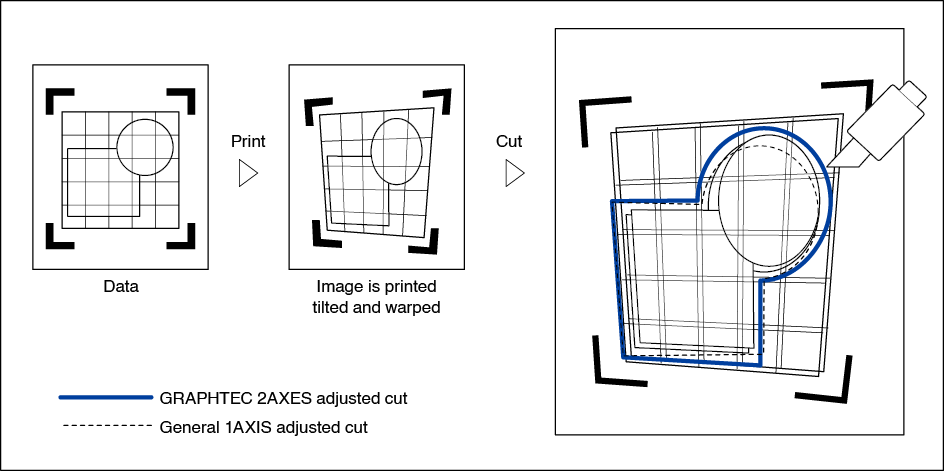
Adjust with 4 POINTS
4 POINTS adjustment will scan 4 registration marks in the corners, where the adjustment is done measuring the tilting of the X and Y axes and the distance between each of the registration marks. It will perform 2 axes warp adjustment in addition to the 2 axes (tilt) adjustment and distance adjustment, so it can adjust more precisely than other methods.
6.2 Manual Position Adjust
Method of manual position adjust is described here.
• Adjustment will be cleared if following is done.
– Set new origin point.
– Set the media again.
– Set rotation or mirror. (Set the rotation or mirror prior to the axis adjustment)
Axis adjustment will convert in accordance with rotation or mirror in this case.
• When the inclination of the axis is too large when setting the first and second point, the first and third point, the third and fourth point, or the second and fourth point, “Angle adjustment error, please reset” will be displayed. After setting the media so as to make the inclination small, please perform adjustment operations.
• Axis adjustment will be cleared when point 1 and point 2 is set to same point.
Operation
1. Load the media on which the registration mark patterns are printed.
Confirm that the push roller is steadily on the media within the range of media movement.
This adjustment is based on assumption that media is slightly tilted.
Media might fall off if the tilting of the media is too large.
2. Set a cutter plunger or a pen in the tool holder.
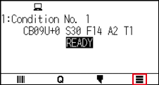
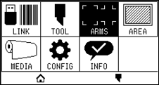
3. Press the [ ] icon.
4. Press the [ARMS].
5. Press the [ ] icon.
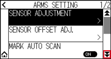
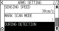
6. Press the [MARK SCAN MODE].
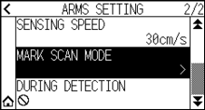
7. Press the [MARK SCAN MODE].
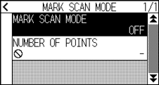
8. Press the [AXIS ALIGNMENT].
9. Press the [NUMBER OF POINTS].
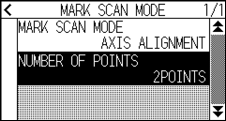
10. Press the number of points you want to use.
Please refer to the following for adjustments when matching the manual position.
• 2 points matching, [“Point 1” settings] [“Point 2” settings] [“Origin point of the axis adjustment” settings] [Finish]
• 3 points matching, [“Point 1” settings] [“Point 2” settings] [“Point 3” settings] [“Distance between Point 1-2” settings] [“Distance between Point 1-3” settings] [“Origin point of the axis adjustment” settings] [Finish]
• 4 points matching, [“Point 1” settings] [“Point 2” settings] [“Point 3” settings] [“Point 4” settings] [“Distance between point 1-2” settings] [“Distance between point 1-3” settings] [Finish]
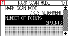
11. Press the [ ] icon.
12. Press the [DURING DETECTION].
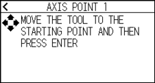
13. Press the POSITION ( ,
,  ,
,  ,
,  ) key to move it to the adjustment mark position.
Pressing the POSITION and [SLOW] keys at the same time will move the tool carriage slower.
14. Confirm the position of the tool and press the [ENTER] key.
 Set adjustment points 2 to 4 in the same way. (The number of adjustment points varies depending on the [NUMBER OF POINTS] setting.)
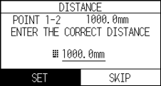
When the adjustment point specification is completed, the DISTANCE screen will be displayed.
15. Press the number or the [ ] icon.
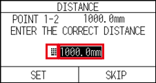
• Measured distance is displayed in the top line in the DISTANCE input screen. Input value (initially same as measured value) is displayed under that.
• If the input value is not changed, it will assume that there is no difference between measured distance and the distance in the data.
16. Specify the setting value using the [] [ ] icon or the [] icon.
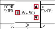
17. Confirm the setting and press the [OK].
18. Press the [SET].
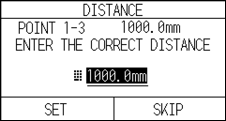
If [NUMBER OF POINTS] is set to 3 or more points, the DISTANCE screen for points 1-3 will be displayed.
Repeat steps 15 to 17 to set the settings.
19. Press the POSITION (, , , ) keys and move the tool carriage to the origin point.
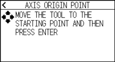
This is displayed only when [NUMBER OF POINTS] is set to 2 POINTS or 3 POINTS.
20. Confirm the tool position and press the [ENTER] key.
21. Press the [ ] icon.
It will return to HOME screen.