Chapter 7:
Settings Regarding Cutting Quality
There are times that ideal cutting may not be possible, such as the lines may shift, corners deform, or uncut sections occur, due to the characteristics of the media (thickness, how hard it is, etc.) or the shape of the blades, when the actual cutting is done. Adjust the moving speed and force of the tool, and the control method to prevent these problems.
This chapter describes the setting regarding the quality of the cutting.
7.1 Cutting the Corner of Thick Media Sharp
Outline of tangential mode
The blade needs to be facing toward the direction of cut when cutting the media. The tip of the blade is shaped as shown so the blade is facing the cutting direction even when it is cutting curved lines or corners. The tip of the blade is off from the rotation axis of the blade (CUTTER OFFSET). The blade will automatically turn and face the cutting direction when the tool carriage moves, because the blade is forced to move from the rotation center, and the blade tip gets resistance by the media.
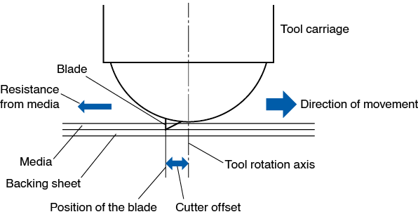
The blade tip gets sunk into the media with 0.3 mm or thicker, making the blade hard to rotate. Especially for the corners where two straight lines meet, cutting becomes very hard because it cannot rotate smoothly.
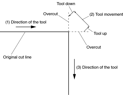
Tangential mode is a control method to precisely cut corners where two straight lines meet.
With the tangential mode, the blade is advanced so it will overcut at the corners before raising the tool. Then, it will be lowered at the position slightly before the next line, and start to cut with slight overcut.
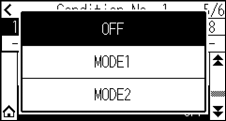
There are 2 modes for tangential mode.
Mode 1: Overcuts the start and end points and acute-angle corners to eliminate uncut sections. In addition, the cutter blade is moved on the surface of the medium during cutting when it is rotated significantly, ensuring sharp cutting unaffected by the hardness or thickness of the media.
Mode 2: Overcuts the start and end points only. In addition, the cutter blade is rotated on the medium surface for the start cutting position only. Mode 2 uses simpler cutter control than Mode 1, and provides a shorter cutting time.
The length of the overcuts by tangential mode can be set individually for start of the line and for end of the line.
Setting the tangential mode
Enabled (Mode 1 and Mode 2) and OFF of the tangential mode can be set individually for each of tool condition No. 1 to 8.
Operation
1. Press the [ ] icon.
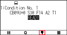
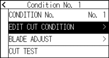
2. Press the [EDIT CUT CONDITION].
3. Press the [ ] icon four times.
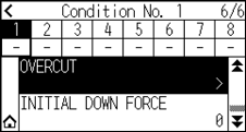
4. Press the tool condition number (1 to 8) you want to set.
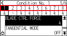
5. Press the [TANGENTIAL MODE].
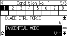
6. Press the mode you want to use.
7. Press the [ ] icon.
 It will return to HOME screen.
Setting the length of overcut
Set the length of overcut with tangential mode.
Operation
1. Press the [] icon.
2. Press the [EDIT CUT CONDITION].
3. Press the [] icon five times.
4. Press the tool condition number (1 to 8) you want to set.
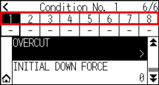
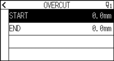
5. Press the [OVERCUT].

It is enabled when Tangential Mode is set.
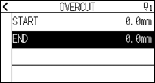
6. Press the [START].
7. Specify the setting value using the [ ] [
] [ ] icon or the [
 ] icon.
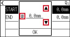
You can set the range between 0.0 mm and 0.9 mm.
8. Confirm the setting and press the [OK].
9. Press the [END].
10. Specify the setting value using the [] [ ] icon or the [] icon.
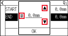
You can set the range between 0.0 mm and 0.9 mm.
11. Confirm the setting and press the [OK].
12. Press the [ ] icon.
13. Press the [] icon.
It will return to HOME screen.
Setting of the Initial Down Force
The initial down-force setting is effective when tangential mode is selected.
Tangential mode is generally used for the cutting of thick media. With thick film, additional time is required for the cutter blade to penetrate the media fully, even when the necessary cutting force is applied.
The cutting operation starts before the cutter blade has fully penetrated the media, causing uncut sections to be left.
When the initial down force is specified, this force is used as the cutting force immediately after the lowering of the tool when tangential mode is selected, enabling the cutter blade to penetrate the media rapidly. (As an example, if the cutting force is 25 and the initial down force is 4, for example, the cutting force applied immediately after the pen is lowered will be 29.) The upper limit for added value is 38.
Operation
1. Press the [] icon.
2. Press the [EDIT CUT CONDITION].
3. Press the [] icon five times.
4. Press the tool condition number (1 to 8) you want to set.
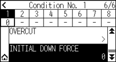
5. Press the [INITIAL DOWN FOECE].
6. Specify the setting value using the [] [] icon or the [] icon.
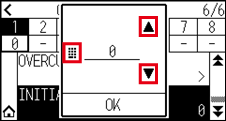
You can set the range between 0 and 20.
7. Confirm the setting and press the [OK].
8. Press the [] icon.
It will return to HOME screen.
7.2 Setting the Step Pass
It may not cut the curved line smoothly if there is very short lines in the curve.
It will cut in the units of the specified value when the STEP PASS is used, which allows to control the short lines with certain length, resulting to stable rotation of the blade for higher cut quality.
Setting range of STEP PASS is from 0 to 20.
Actual length of the STEP PASS is the value of the STEP PASS multiplied by the distance set in the "STEP SIZE".
• This setting will be saved even if the power is shut off.
• The cut image may not be what you intended if the set value is too large.
It is recommended to set to “1” for normal use.
Operation
1. Press the [ ] icon.
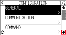
2. Press the [CONFIG].
3. Press the [] icon.
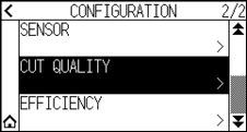
4. Press the [CUT QUALITY].
5. Press the [STEP PASS].
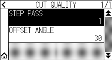
6. Specify the setting value using the [] [] icon or the [] icon.
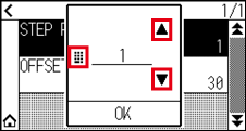
You can set the range between 0 and 20.
7. Confirm the setting and press the [OK].
8. Press the [] icon.
It will return to HOME screen.
7.3 Setting the Offset Angle
The CE8000 analyzes the cutting data, and controls the angle of the cutter blade tip if the change in the angles of the corner is large.
Angle control is applied if there is larger angle change than the angle specified as reference angle.
The time to cut is shortened by setting large value for the OFFSET ANGLE, since it will only apply blade control when there are angles with large angle change, hence this saves time and reduces the overall cutting time. But, if it is set too large, there will be not enough angle control of the blade, and the cut result may differ from what was expected. Set the reference angle in good balance.
The setting will be saved even if the power is shut off.
Operation
1. Press the [] icon.
2. Press the [CONFIG].
3. Press the [] icon.
4. Press the [CUT QUALITY].
5. Press the [OFFSET ANGLE].
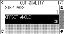
6. Specify the setting value using the [] [] icon or the [] icon.
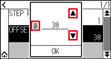
You can set the range between 0 and 60.
7. Confirm the setting and press the [OK].
8. Press the [] icon.
It will return to HOME screen.
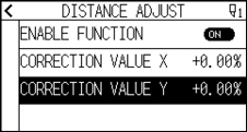
7.4 Setting the Distance Adjust
DISTANCE ADJUST value corrects any deviation in the length of cut or plotted line segments, which occurs depending on the media being used.
DISTANCE ADJUST value for the deviation is specified as a percentage of the total distance. For example, a setting of +0.05% adjusts a distance of 2 m (2,000 mm) by 2,000 x 0.05% = 1 mm, making 2,001 mm. DISTANCE ADJUST can be specified for each CONDITION No.
This setting will be saved even if the power is shut off.
Operation
1. Press the [] icon.
2. Press the [EDIT CUT CONDITION].
3. Press the [] icon three times.
4. Press the tool condition number (1 to 8) you want to set.
5. Press the [DISTANCE ADJUST].
6. Press the [ENABLE FUNCTION] to turn it to [ON].
To cancel, set it to [OFF].
7. Press the [CORRECTION VALUE X].
8. Specify the setting value using the [] [] icon or the [] icon.
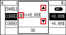
You can set the range between -2.00% and +2.00%.
9. Confirm the setting and press the [OK].
10. Press the [CORRECTION VALUE Y].
11. Specify the setting value using the [] [] icon or the [] icon.
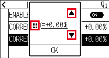
You can set the range between -2.00% and +2.00%.
12. Confirm the setting and press the [OK].
13. Press the [] icon.
14. Press the [] icon.
It will return to HOME screen.
7.5 Setting Cut Line Pattern
To prevent cut media from falling off while you work, you can change the cutting line to the perforated lines.
There are 8 different patterns of perforated lines set as 0 to 7, and the ratio of cut and uncut part differs in each. The uncut part becomes shorter with smaller value, making it easier to separate the cut parts.
Every time the machine cuts 8 mm, the tool will be raised by the following length or the FORCE (cutting pressure) will be reduced to avoid cutting.
• Pattern 0: 0.15 mm • Pattern 1: 0.20 mm • Pattern 2: 0.25 mm • Pattern 3: 0.30 mm
• Pattern 4: 0.35 mm • Pattern 5: 0.40 mm • Pattern 6: 0.45 mm • Pattern 7: 0.50 mm
In addition to above 8 patterns, "OFF" which cuts by the solid line without perforation patter and "USER" where user can specify a unique pattern are provided.
The processing in the part is not cut with perforation patter is adjusted in "GAP ACTION ".
The perforation patter can be set for each condition number.
• Normally use it with default value OFF. It will cut with solid line.
• Use Tool Holder (forward) when cutting with any perforation pattern (aside from turning it off).
See “2.2 Attaching a Tool” for detailed usage instructions.
• Doing a cut-out (cutting out) with a perforated pattern instead of a normal film cut (half cutting) can damage the cutting mat and the quality of a normal cut. Please make sure to use Tool Holder (backward).
• Replacing a cutting mat that was damaged by doing a perforated cut with use of Tool Holder (backward) will require a service fee.
• When the tool number is switched between the Tool No. 1 and the Tool No. 3 using the command from the computer, the following message will appear.
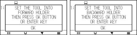
Please follow the message’s instructions.
• The cut on the perforation pattern is shortened by 5 mm on the +X side (back of the media).
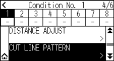
Operation
1. Press the [] icon.
2. Press the [EDIT CUT CONDITION].
3. Press the [] icon three times.
4. Press the tool condition number (1 to 8) you want to set.
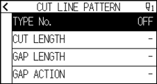
5. Press the [CUT LINE PATTERN].
6. Press the [TYPE No.].
7. Display the TYPE No. you want to use using the [] and [ ] icons.
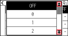
8. Press the Type No. you want to use.
9. Press the [GAP ACTION].
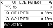
10. Specify the setting value using the [] [] icon or the [] icon.
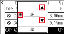
• You can set the range between 1 and 38, or “UP”.
• Value set here will be the cut force for the uncut part of the perforated lines.
Tool will be raised when set to “UP”.
• Normally, input the smaller value than the FORCE for cutting to make it half cutting.
11. Confirm the setting and press the [OK].
12. If the "USER" is chosen in step 7, set the [CUT LENGTH] and [GAP LENGTH].
Follow steps 10 to 11 for this operation.
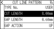
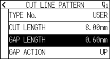
• If the TYPE No. 0 to 7 is selected in step 7, CUT LENGTH and GAP LENGTH is only displayed, and not possible to change.
•Range possible to set for the CUT LENGTH is 0.01 mm to 500.0 mm.
•Range possible to set for the GAP LENGTH is 0.01 mm to 10.0 mm.
13. Press the [] icon.
14. Press the [] icon.
It will return to HOME screen.
7.6 Setting Initial Blade Control Position Adjust
After turning on the power or changing pen condition settings, touch the blade to the media and adjust the blade direction. The Initial Blade Control Position will need to be set in order to make sure the area is not damaged and that the blade properly makes contact with the media.
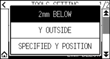
Selecting "2mm BELOW" will change the Initial Blade Control Position to 2 mm below the cutting start point (2 mm from the edge of the point from which the media will be shifted.)
Selecting "Y OUTSIDE" will initialize Initial Blade Direction Setting outside the cutting area.
Selecting "SPECIFIED POSITION" will initialize Initial Blade Direction Setting at the Y direction fixed position that has been set.
* When media narrower than the set Y position is set, it will be the Y maximum value.
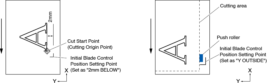

Selecting [Y OUTSIDE] and then changing the expand setting to a positive digit (8 mm ABOVE) can damage the cutting mat.
Operation
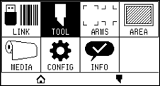
1. Press the [] icon.
2. Press the [TOOL].
3. Press the [INITIAL B. ANGLE POSITION].
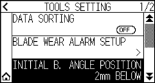
4. Press the blade initialization position you want to use.
• “Y SPECIFIED POSITION “ is displayed when media is loaded.
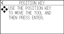
• If you select [SPECIFIED Y POSITION] in the ready state, the following message will be displayed.
Press the POSITION ( ,
,  ,
,  ,
,  ) key to move the tool position, and press the [ENTER] key to set.
5. Press the [] icon.
It will return to HOME screen.
7.7 Setting the blade control force
Slight cut operation is performed before the actual cut operation to align the blade toward the cutting direction.
Lower FORCE is necessary compared with the normal cutting, so it is possible to set lower FORCE as a BLADE CTRL FORCE.
BLADE CTRL FORCE is used to control the rotation of the blade with the tangential mode in addition to control the blade direction at the beginning of the cut.
Operation
1. Press the [] icon.
2. Press the [EDIT CUT CONDITION].
3. Press the [] icon four times.
4. Press the tool condition number (1 to 8) you want to set.
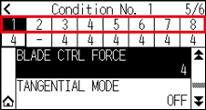
5. Press the [BLADE CTRL FORCE].
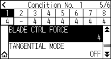
6. Specify the setting value using the [] [] icon or the [] icon.
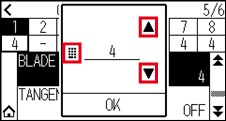
You can set the range between 1 and 38.
7. Confirm the setting and press the [OK].
8. Press the [] icon.
It will return to HOME screen.
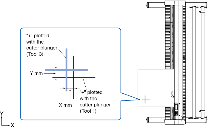
7.8 Setting Adjustment Between the Tools
If there is a misalignment between the tools, you can correct the misalignment by using this function.
If there is a misalignment in the cutting/plotting between Tool 1 (tool attached to the backward of the tool holder) and Tool 3 (tool attached to the forward of the tool holder), you can correct it by entering the adjustment value.
Set “ASSIGN TOOL” of tool condition 1 to 1 and set “TOOL” to Pen.
Set “ASSIGN TOOL” of tool condition 2 to 3 and set “TOOL” to Cutter.
Operation
1. Press the [] icon.
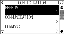
2. Press the [CONFIG].
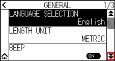
3. Press the [GENERAL].
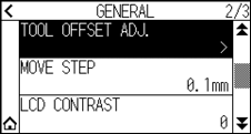
4. Press the [] icon.
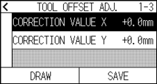
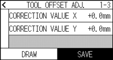
5. Press the [TOOL OFFSET ADJ.].
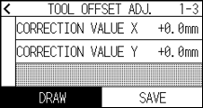
6. Press the [DRAW].
7. Press the POSITION (, ,  ,
,  ) keys to move the tool carriage and the media to the position where the test pattern is cut.
Move it inside of a cutting area greater than 50 mm on both the X and Y axes.
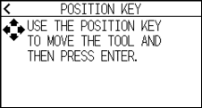
Pressing the POSITION and [SLOW] keys at the same time moves the tool carriage slowly.
8. Confirm the tool position and press the [ENTER] key.
Using the pen plunger (Tool 1), plot a “+” mark.
Next, using the pen plunger (Tool 3), plot a “+” mark.
When plotting is completed, TOOL OFFSET ADJ. screen is displayed.
9. Using “+” plotted with the pen plunger (Tool 1) as a reference, measure how much the “+” cut by the cutter plunger (Tool 3) deviates. (For example, in the case shown in the figure, it is deviated in the -X direction / + Y direction, so enter X = + * mm, Y = - * mm.)
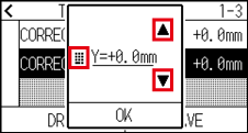
10. Press the [CORRECTION VALUE X].
11. Specify the setting value using the [] [] icon or the [] icon.
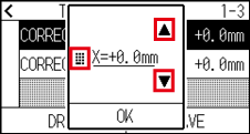
You can set the range between -3.0 mm and +3.0 mm.
12. Confirm the setting and press the [OK].
13. Press the [CORRECTION VALUE Y].
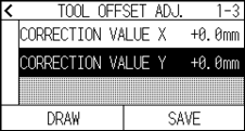
14. Specify the setting value using the [] [] icon or the [] icon.
You can set the range between -3.0 mm and +3.0 mm.
15. Confirm the setting and press the [OK].
16. Repeat steps 6 to 14 until the misalignment between the two tools is corrected.
17. Press the [SAVE].
18. Press the [] icon.
19. Press the [] icon.
It will return to HOME screen.