Chapter 3: Basic Operations
This chapter describes the basic methods to operate the plotter manually.
3.1 Raise or Lower the Tool
This is a function to raise or lower the tool.
Operation
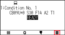
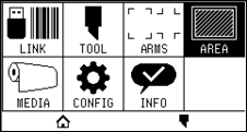
1. Press the [ ] icon.
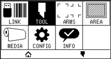
2. Press the [TOOL].
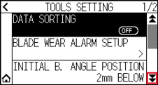
3. Press the [ ] icon.
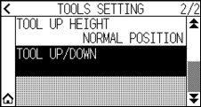
4. Press the [TOOL UP/DOWN]. Tool is raised or lowered every time the [TOOL UP/DOWN] is pressed.
5. Press the [ ] icon.
 It will return to HOME screen.
3.2 Move the Tool Carriage
Tool carriage can be moved manually using the POSITION key.
It can move the tool carriage to the origin, or move it certain distance to keep it away.
Move in steps manually
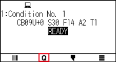
It can manually move in steps when the screen is displaying "READY", or when the POSITION ( ,
,  ,
,  ,
,  ) key is displayed.
Operation
1. Press the POSITION (,  , , ) key once to move in the desired direction.
Tool carriage or the media will move toward the direction of the pressed POSITION key for 1 step.

• It will move in steps every time POSITION ( ,
,  ,
,  ,
,  ) key is pressed.
• Distance of step movement can be changed. See “3.2 Move the Tool Carriage”.
Continuously move manually
It can manually move continuously when the screen is displaying "READY", or when the POSITION (, , ,  ) keys are displayed.
Operation
1. Hold the POSITION (, , , ) key down to keep moving in the desired direction.
Tool carriage or the media keeps on moving continuously in the direction of the pressed POSITION key.
Pressing the POSITION and [SLOW] keys at the same time will move the tool carriage slower.
2. Release the POSITION (, , , ) key.
Movement of the tool carriage or the media will stop.
Setting step movement distance
The parameters when setting the cutting direction are determined by the distance of the cutting direction.
Operation
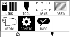
1. Press the [] icon.
2. Press the [CONFIG].
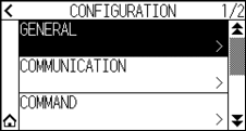
3. Press the [GENERAL].
4. Press the [] icon.
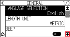
5. Press the [MOVE STEP].
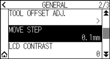
6. Press the move step you want to use.
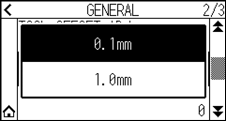
Value chosen here will be the movement distance for the step movement.
7. Press the [] icon.
It will return to HOME screen.
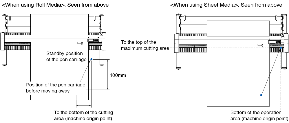
Move away the tool carriage
It is possible to move the tool carriage toward upper right.
It makes it easier to confirm the cutting results if you perform this operation after the cutting is completed.
Operation
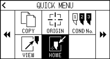
1. Press the [ ] icon.
2. Press the [VIEW].
Tool carriage will move away.
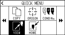
3. Press the [HOME].
Tool carriage will move to the origin point.
Reset (Revert to the initial state when the power was turned on.)
Revert to the initial state when the power was turned on.
Operation
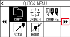
1. Press the [] icon.
2. Press the [ ] icon.
3. Press the [RESET].
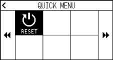
4. Press the [YES].

3.3 Setting the Origin Point
Point where the plotting starts is called origin point. The origin point can be set at any location.
How to set the current position to the new origin point
1. Move the tool to the new origin point by pressing the POSITION (, , , ) keys when it is in READY status.
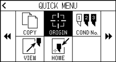
2. Press the [] icon.
3. Press the [ORIGIN].
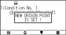
4. "NEW ORIGIN POINT IS SET!" is displayed for few seconds in the screen.
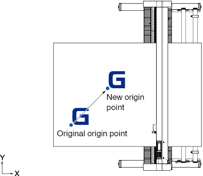
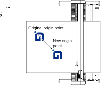
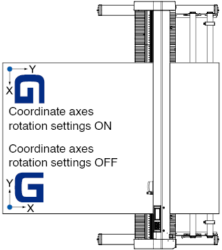
When coordinate axes rotation are set
If the origin point is moved while the coordinate axes are rotated, the origin point will move as shown below.
See “3.4 Setting the Cutting Direction” about the rotation of the coordinate axes.
When coordinate axes are rotated after origin point is set
The origin point will be initialized as shown below if the coordinate is rotated after moving the origin point.
Distance "a" will be maintained, but distance "b" will be initialized.
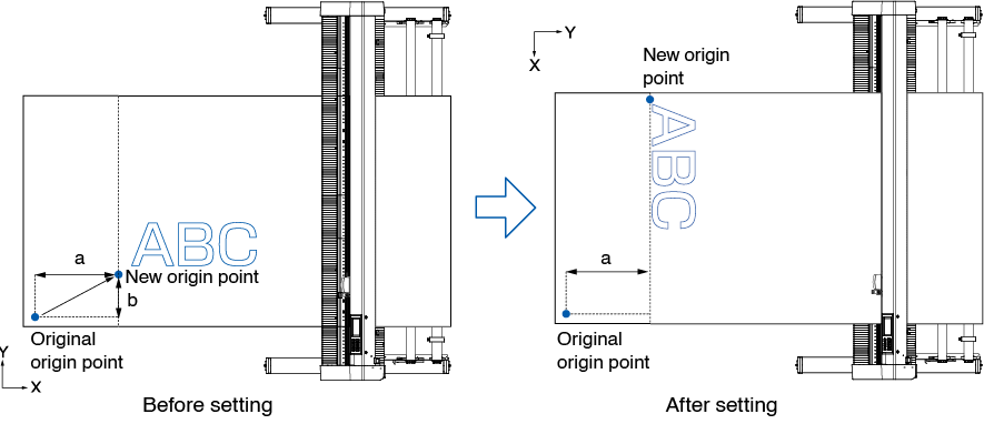
• To use the origin point movement and coordinate axes rotation together, always rotate the coordinate axes first, and then move the origin point.
• Coordinate value displayed after setting new origin point is a distance from the new origin point.
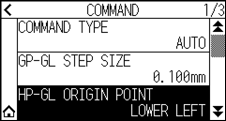
Setting origin point when HP-GL is set
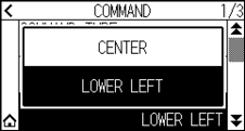
When using the HP-GL command, the origin point is set to either the lower left of the cutting area or the center.
• When using the GP-GL command, this setting does not affect the operation.
• See “Chapter 11 Settings of Controls from Computer” for setting the COMMAND.
Operation
1. Press the [] icon.
2. Press the [CONFIG].
3. Press the [COMMAND].
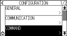
4. Press the [HP-GL ORIGIN POINT].
5. Press the origin position you want to use.
6. Press the [] icon.
It will return to HOME screen.
3.4 Setting the Cutting Direction
Rotate the coordinate axes to change the cutting direction.
The rotation settings will be saved even if the power is shut off.
Operation
1. Press the [] icon.
2. Press the [AREA].
3. Press [ROTATE] to turn it to [ON].
To cancel, set it to [OFF].
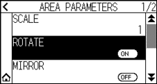
4. Check the settings and press the [] icon.
5. The tool carriage moves to the set coordinate position.
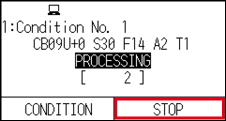
3.5 Stop Cutting
It will stop cutting during operation.
The menu is displayed on the screen of the control panel while it is stopped. It is possible to choose either to continue or stop the operation.
It is also possible to exchange or reset the media while it is stopped.
Pause and resume cutting
Operation
1. Press the [STOP] or [ESCAPE] key.
2. Perform necessary operation, such as exchanging the media.
There is no effect on the selection of media type when the media set lever is moved up and down while pausing the cutting. It is also possible to exchange or reset the media.
3. Press the [RESUME JOB].

Press the [CANCEL JOB] to cancel the cutting.
Stop cutting
Operation
1. Press the [STOP] or the [ESCAPE] key.
2. Press the [CANCEL JOB].

It will resume cutting by pressing the [RESUME JOB].
3. Confirm if the data transfer from the computer is stopped and press the [YES, CLEAR].

The buffer memory will be cleared and it will return to HOME screen.
• If you press the [NO], you will return to the work interruption screen without clearing the buffer memory.
• When clearing the buffer memory, be sure to make sure that data transfer has stopped.
If you clear the buffer memory while data is being transferred, processing will start from the middle of the data, which may result in abnormal operation.