Chapter 15: Troubleshooting
Refer to this chapter if you feel something is wrong, or it does not work right.
It also describes the settings of the plotter, confirming the cutting data, and method to create test patterns.
15.1 Troubleshooting
When the plotter does not operate after turning the power on
|
Symptom |
Possible Cause |
Solution |
|
• Nothing is displayed on the LCD panel. |
There is no power supplied. Or, the plotter is defective. |
Check that the power cord is securely connected to the plotter's AC line inlet and the electrical outlet. Check that the power is supplied to the electrical outlet. Contact your sales representative if the problem still exists. |
|
• "Sum-Ck ROM RAM ERR!!" is displayed on the LCD panel. |
The ROM or RAM is defective. |
Contact your sales representative if the problem still exists. |
When it does not work right
|
Symptom |
Possible Cause |
Solution |
Reference |
|
• Drops the media while detecting. |
Bright light might be shining onto the media sensor. |
Block the light if there is direct sunlight shining on the plotter that is placed near the window. |
|
|
Media sensor may be defective. |
Contact your sales representative if the problem still exists. Set the media sensor to DISABLED to use the plotter temporarily. |
Enabling/Disabling the Media Sensors (MEDIA SENSOR) |
|
|
• Media wobbles. |
Push rollers are not set correctly on the grit rollers. |
Check the position of the push rollers. |
Loading Media (Paper or Marking Film) |
|
Changing of the hold-down force of the push roller is not suitable for the media. (CE8000-130 only) |
Please set a media suitable for changing the hold-down force. |
Changing the Hold-down Force |
|
|
• Tool carriage hits the left side of the plotter and "POSITION ALARM" is displayed after selecting the media type. Or, it hits the right side of the plotter and "POSITION ALARM" is displayed. |
Push roller sensor may be defective if it hits the left side of the plotter. Home sensor may be defective if it hits the right side of the plotter. |
Contact your sales representative if the problem still exists. Set the push roller sensor to DISABLED to use the plotter temporarily. |
Enabling/Disabling the Push Roller Sensors |
|
• The plotter stops with "POSITION ALARM" displayed during initialization or cutting. |
CONDITION setting for the media is invalid. |
Slow down the speed or lower the FORCE. |
Setting the Tool Condition |
|
The pen carriage does not move by hitting something. |
Move the object disturbing the operation, and turn on the plotter after turning it off once. |
||
|
External force is applied to the pen carriage while cutting. |
Move the object disturbing the operation, and turn on the plotter after turning it off once. |
||
|
Movement is disturbed by the media chaff in the operation area. |
Move the object disturbing the operation, and turn on the plotter after turning it off once. |
||
|
The plotter is defective. |
Contact your sales representative if the problem still exists. |
||
|
• It is cutting with origin point shifting to center of the media. |
Data created with lower left origin point is received when the plotter is set with center origin point. (With HP-GL command) |
Reset the origin point to center on the application software, or reset the origin point of the plotter to lower left. |
Setting Origin Point When HPGL is Set |
|
• Media jumps out to forward side. |
Selected wrong type of the media. |
Check the type of media, "SHEET", "ROLL-1 FRONT EDGE", or "ROLL-2 CURRENT POSITION". |
Setting Feeding Method |
|
• Displays command error. |
Data sent to the plotter is not correct. |
Check the data. |
Error Message in GP-GL Command Mode |
|
• It cannot cut above certain length. |
Length of the cut is exceeding the length of the page set on the plotter. |
Press the [SLOW] key and check the cutting area. |
Setting Length of the Page |
|
• There are too many tool up and down. |
Setting for the tangential mode is set to ON. |
Turn OFF the setting for the tangential mode unless you are cutting thick media. |
Setting the TANGENTIAL MODE |
|
• It is cutting on the grit roller imprint. |
Cutting width is widened. |
Please turn OFF the expand setting. |
Setting Cutting Width |
|
• Cannot change the tool condition. |
Setting for the sorting is set to ON. |
Normally, use the plotter with setting for the sorting OFF. |
Sorting the Cutting Data |
|
• Tool condition changes. |
Setting of the priority is set to COMMAND PRIORITY. |
Change the setting of the priority to MENU PRIORITY. |
Priority of Cut Condition Selection. |
|
[ENTER] key is not pressed after changing the TOOL CONDITION. |
Check the TOOL CONDITION again. |
Setting the Tool Condition |
|
|
• Media travels tilted. |
Media is loaded tilted. |
Reload the media. |
Loading Media (Paper or Making Film) |
|
Media is slipping. |
Perform pre feed once and make impression to make it harder to slip. |
Pre Feed of Media (Paper or Marking Film) |
|
|
Changing of the hold-down force of the push roller is not suitable for the media. |
Please set a media suitable for changing the hold-down force. |
Changing the Hold-down Force |
|
|
• It does not become specified length. (Slight distance error) |
Media is slipping. |
Make the speed slower. |
Setting the Tool Condition. |
|
Distance adjust value is not correct. |
Perform distance adjust. |
Setting the Distance Adjust |
|
|
• "LOAD MEDIA!" is displayed even if the media is set and media set lever is moved up. |
Media is close to transparent and media sensor makes false recognition. (This may happen depending on the media.) |
Transparent media cannot be detected. DISABLE the media sensor and set the cutting area when this kind of media is used. |
Enabling/Disabling the Media Sensors Setting Cutting Area |
|
Media sensor malfunctions with strong scattered reflection. |
Move the position of the light source. |
||
|
There may be defective in the operation of the media set lever sensor. |
Contact your sales representative if the problem still exists. |
||
|
• Touch panel does not respond. |
The touch panel installed on this plotter is a capacitive type. Insulated touch pens (pressure-sensitive) will not respond. |
Use your finger or a capacitive touch pen. |
|
|
• Wireless LAN access point cannot be found. |
The wireless LAN compatible standard of this plotter is 802.11b/g/n (2.4GHz). It does not support the 5GHz frequency. |
Please use an access point that supports the wireless LAN compatible standard 802.11b/g/n (2.4GHz). |
When the Cutting Result is Not Good
|
Symptom |
Possible Cause |
Solution |
|
• Corners are rounded. • Corners are too sharp. |
Blade and OFFSET does not match. |
Change the OFFSET.
|
|
• The cut line starts out crooked. |
The blade inside the plunger doesn't turn smoothly. |
Remove dirt from inside the plunger. |
|
• The blade skips and does not completely cut lines that should be solid. • Straight cut lines seems to wobble. |
The blade is extended too far. |
Adjust the blade length. |
|
The cutting speed is too high. |
Lower the speed setting. |
|
|
• Coarse resolution of curved lines. |
The software's resolution setting is too low. |
Adjust the software's resolution setting. |
|
The blade offset angle is too low. |
Increase the value for the blade offset angle. |
|
|
• The media curls up at the corners. • Fine cut characters peels off. |
The blade is extended too far. |
Adjust the blade length. |
|
Blade and OFFSET does not match. |
Change the OFFSET. |
|
|
The cutting speed is too high. |
Lower the speed setting. |
|
|
The blade is dull. |
Replace the blade. |
|
|
The ACCELERATION setting is too high. |
Lower the ACCELERATION setting. |
|
|
• The blade is cutting into the backing sheet. |
The blade is extended too far. |
Adjust the blade length. |
|
The cutting FORCE is too high. |
Lower the FORCE setting. |
|
|
• The blade falls out of the tool plunger. |
The blade is too small for the tool plunger. |
Use a blade that fits securely in the tool plunger. |
|
• Media can be cut but it is hard to weed afterwards. • Cut media cannot be pulled up using retack sheet. |
The retack sheet is not sticky enough. |
Switch to a stickier retack sheet. |
|
Media gets entangled during cutting. |
Reduce the blade length. |
|
|
Lower the FORCE setting. |
||
|
Cleaning of cut media was postponed too long. |
Promptly weed cut media. |
|
|
• Abnormal noise generated from the tool carriage during cutting. • The media is discolored where the blade has passed. |
Media is rubbed by the tip of the tool plunger. |
Adjust the blade length and the cutting FORCE settings. |
|
• The cutting results differ from the specified size. |
The STEP SIZE has been set differently at the computer and the plotter. |
Set the STEP SIZE to same value. |
|
Scaling has been specified on the computer. |
Check whether scaling has been specified. |
|
|
• Currently selected cutting conditions are disregarded or cannot be changed. |
Setting of the priority is set to COMMAND PRIORITY. |
Change the setting of the priority to MENU PRIORITY. |
|
The [ENTER] key was not pressed after changing the settings. |
Check the operation. |
|
|
• Characters or lines are deformed during pen plotting. |
The plotter is in cutting mode. |
Select PEN as the tool in the CONDITION setting. |
|
• It does not become specified length. (Slight distance error) |
Distance adjust value is not correct. |
Perform distance adjust. |
|
• Characters are deformed. • Complex drawings are deformed. |
The STEP PASS setting is set too high. |
Lower the STEP PASS setting. |
|
• The starting and end points of cutting do not match. |
Coordinate points are incorrectly specified. |
Check the coordinate data by plotting it with a pen. |
|
The media backing is too flimsy. |
Switch to a media with a stronger backing. |
|
|
Blade rotation is not smooth. |
Check that there is no dirt in the blade. |
 It is rounded: Increase the OFFSET
 Error Messages in GP-GL Command Mode
|
Error Displayed |
LCD Display |
Cause |
Solution |
|
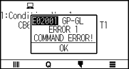
E02001 |
|
The plotter received an unrecognizable command. |
Press the [ENTER] key. |
|
Noise came in when the computer was turned on. |
Configure to drive the plotter from the menu of the software. |
||
|
The software configuration regarding the output device has been changed. |
Reset the interface settings of the software. |
||
|
The plotter's interface conditions have changed. |
Reset the interface settings of the plotter. |
||
|
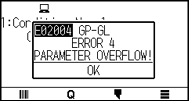
E02004 |
|
A command was received containing numeric parameters that exceed that command's permissible range. |
Configure to drive the plotter from the menu of the software. |
|
The software configuration regarding the output device has been changed. |
Reset the interface settings of the software. |
||
|
The plotter's interface conditions have changed. |
Reset the interface settings of the plotter. |
||
|
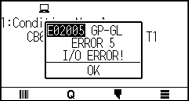
E02005 |
|
An error occurred in the receipt of data within the interface. |
Configure to drive the plotter from the menu of the software. |
|
The software configuration regarding the output device has been changed. |
Reset the interface settings of the software. |
||
|
The plotter's interface conditions have changed. |
Reset the interface settings of the plotter. |
||
|
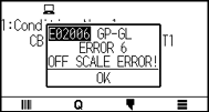
E02006 |
|
The data out of cutting range has been received. |
Check the data. |
|
Check the size of media and the cutting range. |
|||
|
Check the magnification setting. |
|||
|
Check the step size settings. |
Error Messages in HP-GL Command Mode
If any of the following command errors occur, they are nearly always caused by following 2 reasons.
(1) The configuration regarding the output device in the application software has changed.
(2) The plotter's interface conditions have changed.
Perform following if these are the cause of the problem.
(1) Reconfigure the output device of the application software to the plotter.
(2) Reconfigure the plotter's interface conditions.
|
Error Displayed |
LCD Display |
Cause |
Solution |
|
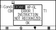
E03001 Error 1 |
|
An unrecognizable instruction was executed. |
Execute a recognizable command. |
|
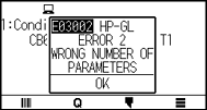
E03002 Error 2 |
|
Wrong number of parameters were specified. |
Execute the command with the correct number of parameters. |
|
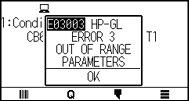
E03003 Error 3 |
|
An unusable parameter was executed. |
Execute a recognizable parameter. |
|
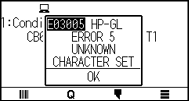
E03005 Error 5 |
|
An unusable character set was specified. |
Specify usable character set. |
|
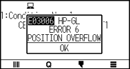
E03006 Error 6 |
|
Coordinates of command specified out of cutting area. |
Execute coordinates within the cutting area. |
|
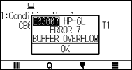
E03007 Error 7 |
|
The data being input exceeds the capacity of the plotter's downloadable character buffer, polygon buffer, etc. |
Adjust the buffer size. |
|
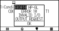
E03010 Error 10 |
|
Other output command was executed while executing an output command. |
Check the program. |
|
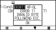
E03011 Error 11 |
|
An invalid byte was received after ESC code. |
Check the program. |
|
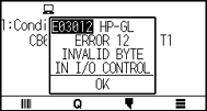
E03012 Error 12 |
|
Invalid byte was received within device control command. |
Check the program. |
|
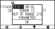
E03013 Error 13 |
|
A parameter outside of the permissible range was specified in the I/O related command. |
Check the program. |
|
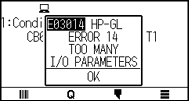
E03014 Error 14 |
|
Too many parameters in the I/O related command. |
Check the program. |
ARMS Error Messages
|
Error Displayed |
LCD Display |
Cause |
Solution |
|
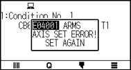
E04001 |
|
Tilt to adjust with AXIS ALIGNMENT is too large. |
Reload the media. |
|
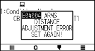
E04004 |
|
It is over the setting range of the distance adjust. |
Reset to smaller value. |
|
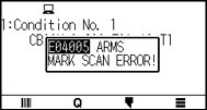
E04005 |
|
Could not scan the registration marks. |
Check the registration scan position. |
|
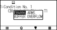
E04006 |
|
Amount of data has exceeded the I/O buffer size for the segment area registration mark. |
Decrease the data. |
|
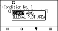
E04007 |
|
Test pattern plotting position is not within the plotting area for sensor position adjustment. |
Move the media toward center and plot the test pattern. |
|
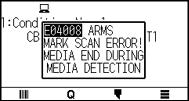
E04008 |
|
Media end was detected while detecting the registration mark. |
Check the media. Check the print position of the registration mark. |
|
E04009 |
|
It has exceeded detection area while detecting the registration mark. |
Check the media. Check the print position of the registration mark. |
|
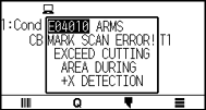
E04010 |
|
It has exceeded detection area while detecting the registration mark. |
Check the media. Check the print position of the registration mark. |
|
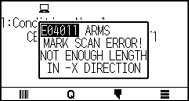
E04011 |
|
It has exceeded detection area while detecting the registration mark. |
Check the media. Check the print position of the registration mark. |
|
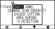
E04012 |
|
It has exceeded detection area while detecting the registration mark. |
Check the media. Check the print position of the registration mark. |
|
E04013 |
|
It has exceeded detection area while detecting the registration mark. |
Check the media. Check the print position of the registration mark. |
|
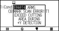
E04014 |
|
It has exceeded detection area while detecting the registration mark. |
Check the media. Check the print position of the registration mark. |
|
E04015 |
|
It has exceeded detection area while detecting the registration mark. |
Check the media. Check the print position of the registration mark. |
|
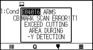
E04016 |
|
It has exceeded detection area while detecting the registration mark. |
Check the media. Check the print position of the registration mark. |
|
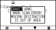
E04017 |
|
It has exceeded detection area while detecting the registration mark. |
Check the media. Check the print position of the registration mark. |
|
E04018 |
|
Media set lever was lowered. |
Reload the media and try again. |
|
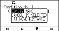
E04019 |
|
There was cancel operation by the user. |
Redo the process. |
|
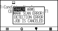
E04020 |
|
There is a defect in the detection settings value. |
Check the settings value. |
|
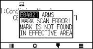
E04021 |
|
Registration mark was not detected in the auto detection area. |
Check the media. Check the print position of the registration mark. |
|
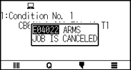
E04022 |
|
There was cancel operation by the user. |
Redo the process. |
|
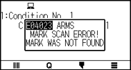
E04023 |
|
Registration mark was not detected. |
Change the color of the registration mark. Check the media. Check the print position of the registration mark. |
|
E04024 |
|
Registration mark was not detected. |
Change the color of the registration mark. Check the media. Check the print position of the registration mark. |
|
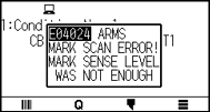
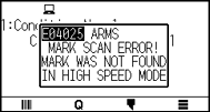
E04025 |
|
Registration mark was not detected. |
Change the color of the registration mark. Check the media. Check the print position of the registration mark. |


Other Error Messages
|
Error Displayed |
LCD Display |
Cause |
Solution |
|
E01001 |
|
The plotter is defective. |
Contact your sales representative if the problem still exists. |
|
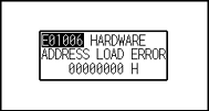
E01006 |
|
The plotter is defective. |
Contact your sales representative if the problem still exists. |
|
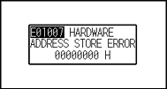
E01007 |
|
The plotter is defective. |
Contact your sales representative if the problem still exists. |
|
E01008 |
|
The plotter is defective. |
Contact your sales representative if the problem still exists. |
|
E01009 |
|
The plotter is defective. |
Contact your sales representative if the problem still exists. |
|
E01010 |
|
The plotter is defective. |
Contact your sales representative if the problem still exists. |
|
E01011 |
|
The plotter is defective. |
Contact your sales representative if the problem still exists. |
|
E01012 |
|
The plotter is defective. |
Contact your sales representative if the problem still exists. |
|
E01013 |
|
The plotter is defective. |
Contact your sales representative if the problem still exists. |
|
E01014 |
|
The plotter is defective. |
Contact your sales representative if the problem still exists. |
|
E01015 |
|
The plotter is defective. |
Contact your sales representative if the problem still exists. |
|
E01017 |
|
Load on the motor was too large. |
Move the object disturbing the operation, and turn on the plotter after turning it off once. |
|
E01019 |
|
Load on the motor was too large. |
Move the object disturbing the operation, and turn on the plotter after turning it off once. |
|
E01021 |
|
Load on the motor was too large. |
Move the object disturbing the operation, and turn on the plotter after turning it off once. |
|
E01022 |
|
There was a heavy load on the up and down function of the tool carriage. |
Please clear any obstruction in the up and down function of the tool carriage and turn the power back on. |
|
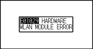
E01029 |
|
An error has occurred in the wireless LAN module. |
Turn the power off and then on again. Contact your sales representative if the error still appears. |
|
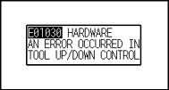
E01030 |
|
There was a heavy load on the up and down function of the tool carriage. |
Please clear any obstruction in the up and down function of the tool carriage and turn the power back on. |
|
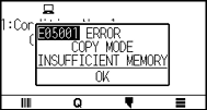
E05001 |
|
Data larger than the buffer size cannot be copied. |
Perform normal cutting not using the copy mode. |
|
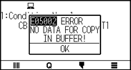
E05002 |
|
There is no data to copy. |
Perform normal cutting by sending the data, then use the copy mode. |
|
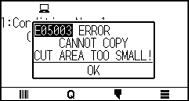
E05003 |
|
Media valid area to copy is too small. |
Use larger media. Confirm the copy start position. |
|
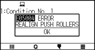
E05004 |
|
The push roller is not on the grit roller. |
Set the push roller on the grit roller. |
|
E05006 |
|
Distance between the bottom left and top right of the AREA setting is less than 10 mm. |
Perform the AREA setting again. |
|
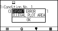
E05007 |
|
Test pattern for the TOOL OFFSET ADJ. cannot start plotting because the start position is at the edge of the media. |
Set the start position inside the media. |
|
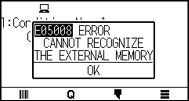
E05008 |
|
External memory (USB memory) cannot be recognized. |
Insert external memory (USB memory). |
|
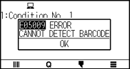
E05009 |
|
Bar Code cannot be scanned. |
Check the print result of Bar Code. |
|
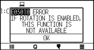
E05010 |
|
Bar Code cutting is not available when Rotation is set to ON. |
Set Rotation is set to OFF to use Bar Code cutting. |
|
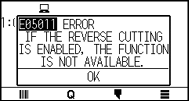
E05011 |
|
Bar Code cutting is not available when Mirror is set to ON. |
Set Mirror is set to OFF to use Bar Code cutting. |
|
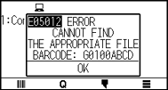
E05012 |
|
The desired file cannot be found in external memory (USB memory). |
Save the desired file in external memory (USB memory). |
|
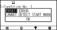
E05013 |
|
Start mark cannot be scanned. |
Check the print result of start mark. |
|
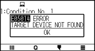
E05014 |
|
The selected connection destination cannot be found. |
Connect to the selected connection destination using USB or LAN cable. |
|
E05015 |
|
There is no appropriate cutting data for the data link server. |
Check the data link server. |
|
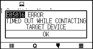
E05016 |
|
The communication to the data link server is not established. |
Check the data link server. |
|
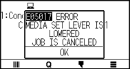
E05017 |
|
Media set lever is lowered. |
Set the media again. |
|
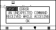
E05018 |
|
A trouble occurs in the data link server. |
Restart the data link server. |
|
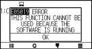
E05019 |
|
A trouble occurs in communication to the data link server. |
Set the media again. |
|
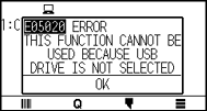
E05020 |
|
The connection destination is not USB memory. |
Set connection destination to USB memory. |
|
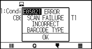
E05021 |
|
The type of bar code is different. |
Apply the appropriate bar code. |
|
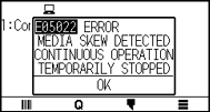
E05022 |
|
Media skew is detected. |
Set the media again. |
|
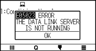
E05023 |
|
Data link server is not activated. |
Activate data link server. |
|
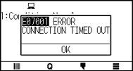
E07001 |
|
Communication with the access point is no longer possible. |
Please check the communication status with the access point. |
|
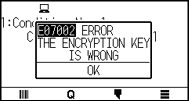
E07002 |
|
The encryption key of access point is incorrect. |
Please enter the correct encryption key of access point. |
|
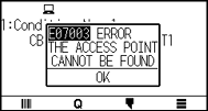
E07003 |
|
No access point was found to connect to. |
Make sure there is an access point nearby and that the access point is turned on. |
|
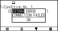
E07004 |
|
Access point connection failed. |
Check the operating status of the access point. |
|
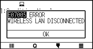
E07005 |
|
Communication with the access point has been disconnected. |
Check the operating status of the access point. |


Caution Message
|
Symptom |
LCD Display |
Description |
|
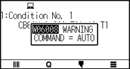
W06008 |
|
When command is set to AUTO, the DUMP mode is not available. |
|
W06009 |
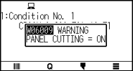
|
When panel cutting has been set to ON, the following functions are not available. • ARMS function • AREA function • COPY function • BARCODE CUT function • CONTINUOUS OPERATION function |
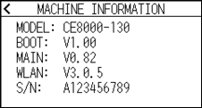
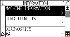
15.2 Check plotter information
Displays information such as the firmware version and serial number of the plotter.
Operation
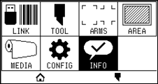
1. Press the [ ] icon.
2. Press the [INFO].
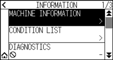
3. Press the [MACHINE INFORMATION].
4. Information about the machine is displayed.
5. Press the [ ] icon.
6. Press the [ ] icon.
 It will return to HOME screen.
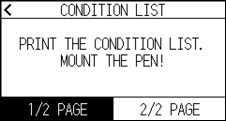
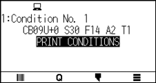
15.3 Printing the Setting of the Plotter
Condition setting list can be printed when you need to check the current setting of the plotter.
Operation
1. Load a media larger than A3 size.
2. Set the pen tool to the tool holder (Backward) and select the condition where the pen tool is set.
3. Press the [] icon.
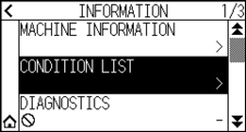
4. Press the [INFO].
5. Press the [CONDITION LIST].
6. Press the [1/2 PAGE] or [2/2 PAGE].
7. Press the POSITION ( ,
,  ,
,  ,
,  ) key to move the tool to the print start position.
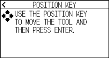
8. Press the [ENTER] key.

Do not place you hand around the moving areas. The tool carriage will start moving, so there is a chance of injury.
9. Printing of the condition list will start.
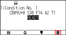
10. It will return to READY status when the printing is completed.

Once printing starts, it cannot be paused or canceled midway.
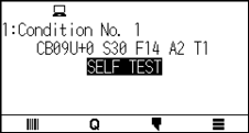
15.4 Creating Test Pattern
Create a self-test pattern to check the operation of the plotter.
Operation
1. Load a media larger than A3 size.
2. Set the pen tool to the tool holder (Backward) and select the condition where the pen tool is set.
3. Press the [] icon.
4. Press the [INFO].
5. Press the [ ] icon.
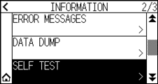
6. Press the [SELF TEST].
7. Press the [START].
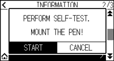
Do not place you hand around the moving areas. The tool carriage will start moving, so there is a chance of injury.
8. The self-test will start.
9. To exit, turn off the power.
Once the self-test starts, it will continue to run until you turn off the power.
15.5 Creating CUTTING PRO
Create a test pattern to check the operation of the plotter.
Operation
1. Load a media larger than A3 size.
2. Select the conditions that comply with the set tool.
3. Press the [] icon.
4. Press the [INFO].
5. Press the [] icon twice.
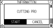
6. Press the [CUTTING PRO].
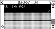
7. Press the [START].
Do not place you hand around the moving areas. The tool carriage will start moving, so there is a chance of injury.
8. “CUTTING PRO” plotting will start.
9. It will return to READY status when the cutting is completed.
15.6 Confirm the Plotting Data
Output of the dump list of the cutting data received by the plotter is possible. It is used to check if the transmission of cutting data is performed correctly.
If the command setting is “Auto”, the dump list of the cutting data is not output.
Please set the command to “GP-GL” or “HP-GL”.
Operation
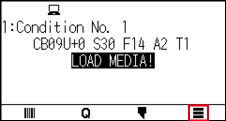
1. Load a media larger than A4 size.
2. Set the pen tool to the tool holder (Backward) and select the condition where the pen tool is set.
3. Press the [] icon.
4. Press the [INFO].
5. Press the [] icon twice.
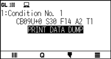
6. Press the [DATA DUMP].
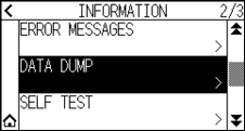
7. Press the [START].
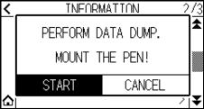
8. Send the cutting data.
Do not place you hand around the moving areas. The tool carriage will start moving, so there is a chance of injury.
9. Outputs the received cutting data as a command.
10. To exit, turn off the power.
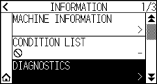
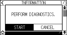
15.7 Self Diagnostic Test
Operation status can be tested by self-diagnostic test by operating the sensors and switches following the instruction on the screen.
Diagnostic test can be performed only right after the power is turned on. DIAGNOSTICS cannot be selected from the menu once any operation, such as loading media, is performed.
Operation
1. Confirm that the power is turned off.
2. Turn the power on without loading the media.
3. Press the [] icon.
4. Press the [INFO].
5. Press the [DIAGNOSTICS].
6. Press the [START].
7. Operate the keys and the sensors following the instructions on the screen.
"OK" will be displayed if the correct operation is detected as a result of the operation, and next test will start.
It will return to the screen shown in step 4 once all the test items are completed.
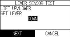
Test items are as following. (It may be changed.)
|
1 |
Set lever sensor |
2 |
Home sensor |
3 |
Push roller sensor |
4 |
-X media sensor |
|
5 |
+X media sensor |
6 |
X motor signal |
7 |
Y motor signal |
8 |
Tool height signal |
|
9 |
[SLOW] key |
10 |
POSITION [ |
11 |
POSITION [ |
12 |
POSITION [ |
|
13 |
POSITION [ |
14 |
[ESCAPE] key |
15 |
[ENTER] key |


8. Press the [] icon.
It will return to HOME screen.
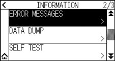
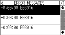
15.8 Reading the error message
Contents of most current 32 errors can be checked.
Operation
1. Press the [] icon.
2. Press the [INFO].
3. Press the [] icon.
4. Press the [ERROR MESSAGES].
ERROR MESSAGES screen is displayed. Left column is time the error occurred, and right column is the type of the error. 3 error messages are displayed at once. If there are more error messages, next 3 messages will be displayed by pressing the [ ] icon.
• “NO ERROR” will be displayed if there is no error.
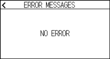
• Up to 32 error messages can be displayed.
• When displayed, while the power is on it indicates how long ago an error occurred.
The lower the value, the more recently the error occurred.
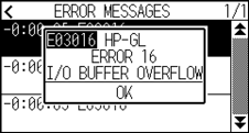
5. Press the error item for which you want to check the error details.
6. Check the error message and press the [OK].
7. Press the [] icon.
8. Press the [] icon.
It will return to HOME screen.